25
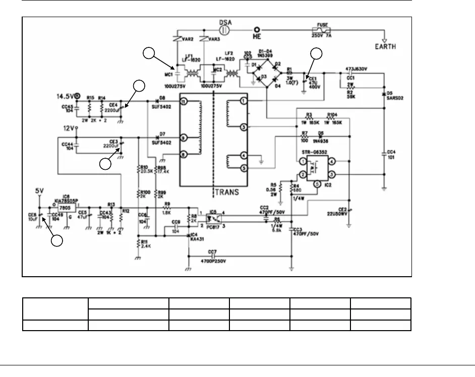
5-1. Power Circuit Diagram
5. CIRCUIT OPERATION
■ FRS(N)-U20IA
5Vdc14.5Vdc12Vdc310Vac230VdcVoltage
CE6CE4CE3CE1MC1
EDCBA
Parts
A
■ 5. CIRCUIT OPERATION. 5-1. Power Circuit Diagram. FRS(N)-U20DA
B
D
C
E
A
B
C
D
E
※ Voltage of every part
※ Caution : Since high voltage (DC310V) is maintained at the power terminal, please take a measure after more
than 3minutes have passed after removing power cords in the abnormal operation of a circuit.