35
5-4. Fan Function
■ FRS(N)-U20IA
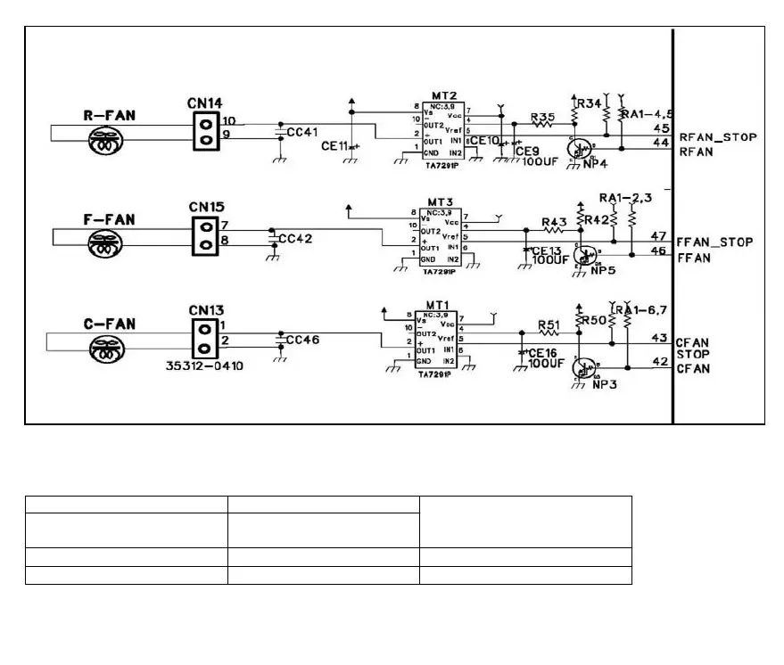
■ 5-3. Fan Function. 1. Circuit Diagram. FRS(N)-U20DA
- Vref is the reference voltage for the adjustment of the output voltage by the voltage
distribution of Vs (Maximum output voltage), and the output voltage applied to the fan
is determined by the PWM control using the software.
2. Explanation for the operation
* TA7291P is the drive IC for the only DC motor, and used for control of the fan motor
* One input and output is used for the control of the fan motor
Motor IC No.2 Pin
(R:MT2/F:MT3/C:MT1)
Motor IC No.5 Pin
(R:MT2/F:MT3/C:MT1)
Low
High
Output
StopLow
13VHigh
Remark
Input
1. Circuit Diagram