Do you have a question about the Daewoo FRN-U20DAI and is the answer not in the manual?
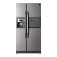
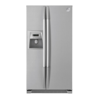
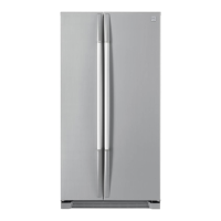
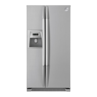
Provides dimensions and diagrams of the refrigerator's external appearance.
Identifies various parts of the freezer and refrigerator compartments with numbered labels.
Illustrates the airflow path within the freezer and refrigerator compartments.
Details technical specifications like volume, dimensions, voltage, weight, and components.
Explains the control panel display and button functions for operation.
Details the display control and specific button functions for the FRS(N)-U20DA model.
Details the defrosting cycle including pre-cool, heater defrost, pause, and fan-delay stages.
Explains the forced defrosting mode procedure and how to start it.
Details the fan voltage settings for different control modes based on sensor inputs.
Explains the control logic for the louver heater, which is linked with the compressor.
Describes when the buzzer sounds for various operations, alarms, and errors.
Explains how refrigerator and freezer compartment lights are controlled by door switches.
Details the procedure for starting, controlling, and stopping the demonstration mode.
Provides instructions on adjusting the R-sensor's ON/OFF point for temperature compensation.
Explains how to start, stop, and interpret error codes displayed on the CLED of the front PCB.
Summarizes element A/S functions and button combinations for various modes on the front PCB.
Explains the filter exchange information and P Factor related to the ice maker.
Details the flow of ice making, including ice making, separating, and water supply modes.
Explains dispenser control functions like initial mode, ice maker lock, and display indicators.
Presents the power circuit diagram for the FRS(N)-U20DA model.
Explains the function, working points, resistance, and voltage of F, R, and D sensors.
Explains the operation of the TA7291P drive IC used for fan motor control.
Provides a detailed wiring diagram connecting various components of the refrigerator.
Shows images of the refrigerator's front, highlighting the location of the front PCB and dispenser button.
Displays images of the freezer and refrigerator compartments, identifying internal components.
Shows an image of the evaporator, labeling key parts like D-Sensor and Defrost Heater.
Displays an image of the machine compartment, identifying components like compressor, condenser, and dryer.
Provides disassembly and checking procedures for the hose ice maker tube assembly.
Details the disassembly and checking procedures for the bracket geared motor and cube solenoid valve.
Explains the disassembly and checking procedure for the dispenser micro switch.
Provides disassembly and checking procedures for the dispenser solenoid valve and flap heater assembly.
Lists items to check on the main PCB, including compensation, relay controller, fan controller, and fuses.
Details the disassembly procedure for the ice maker assembly.
Provides a flowchart for diagnosing issues when the front PCB power is off and lights are off.
Deals with issues in the freezer compartment.
Presents a flowchart for diagnosing freezing failures in the freezer compartment.
Details steps for removing foods, ice bucket, shelves, and specific parts like the ice maker.
Provides a flowchart for diagnosing and resolving ice formation issues on the F-Louver.
Details troubleshooting steps for disconnected or broken freezer light wires and door switch issues.
Deals with issues in the refrigerator compartment.
Presents a flowchart for diagnosing refrigeration failures in the refrigerator compartment.
Details troubleshooting steps for disconnected or broken refrigerator light wires and door switch issues.
Provides a flowchart for diagnosing and resolving dew formation issues in the refrigerator compartment.
Details troubleshooting steps for excessive refrigeration in the vegetable case.
Deals with diagnosing operational noise issues.
Provides a flowchart for diagnosing compressor operation noise issues.
Details troubleshooting steps for sounds related to refrigerant flow, such as water flowing or hissing.
Explains how to troubleshoot hiss, sizzling, and shaking sounds originating from the evaporator.
Provides a flowchart for diagnosing and resolving fan noise issues.
Explains how to fix or fasten the fan motor and address touch sounds from the fan.
Details troubleshooting steps for pipe noises, including touching pipes, tray drip, and compressor vibration.
Deals with issues related to door alarms.
Provides a flowchart for diagnosing why the door opening alarm remains active when the door is closed.
Summarizes the processes, contents, and tools required for heavy cooling cycle repairs.
Lists precautions to be taken during heavy repair, including tool usage and refrigerant handling.
Details practical steps for refrigerant removal, nitrogen blowing, and welding during heavy repairs.
Outlines standard regulations and safety precautions for heavy repair work.
Provides reference drawings for brazing points and the refrigeration cycle flow.
Shows an exploded view of the refrigerator's cabinet, with numbered parts.
Explores exploded views of the mechanical room components with numbered parts.
Explores exploded views of the refrigerator room components with numbered parts.
Explores exploded views of the freezer room components with numbered parts.
Explores exploded views of the freezer door components with numbered parts.
Explores exploded views of the refrigerator door components with numbered parts.
Lists parts for the refrigerator with part codes, names, quantities, and descriptions.
| Brand | Daewoo |
|---|---|
| Model | FRN-U20DAI |
| Category | Refrigerator |
| Energy Rating | A+ |
| Noise Level | 43 dB |
| Refrigerant | R600a |
| Door Storage | Yes |
| Reversible Door | No |
| Voltage | 220-240 V |
| Frequency | 50 Hz |
| Type | Side by Side |