G424 Service Manual Base Engine Service Procedure160
6EN0700
6AE0115
DEN0051
6EN0621
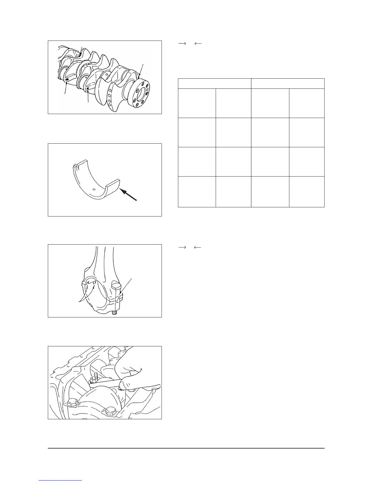
E Connecting rod bearing installation
When the bearings are replaced, select and install them
according to the identification colors on the crankshaft and
identification marks stamped on the connecting rod bearing.
Crankshaft Connecting rod bearing
Pin Pin O.D. Identification Thickness,
identification mm (in.) mark or color mm (in.)
color
Yellow
None
White
F Connecting rod cap installation
(1) Verifying the mark made during disassembly, install the
bearing cap to the connecting rod. If the connecting rod
is new with no index mark, make sure that the bearing
locking notches come on the same side as shown.
(2) Make sure that connecting rod big end side clearance
meets the specification.
Standard value: 0.10 to 0.25 mm (0.0039 to 0.0098 in.)
Limit: 0.4 mm (0.016 in.)
44.995 to
45.000
(1.77145 to
1.77165)
1.487 to
1.491
(0.05854 to
0.05870)
1.491 to
1.495
(0.05870 to
0.05886)
1.495 to
1.499
(0.05886 to
0.05902)
1
or Yellow
2
or None
3
or Blue
44.985 to
44.995
(1.77106 to
1.77145)
44.980 to
44.985
(1.77086 to
1.77106)
Connecting rod inside diameter:
48.000 to 48.015 mm (1.88976 to 1.89035 in.)
Identfication mark
Cylinder No.
Notches
No.4
No.1
No.2
No.3