G420E/G424E Tier LP Engine System Operational Overview 28
The MI-04 system also performs minimum (min) and
maximum (max) governing through the SECM and
DBW throttle. For min governing, or idle speed control,
the idle speed is fixed by the SECM. Unlike a
mechanical system, the idle speed is not adjustable
by the end user. The idle speed is adjusted by the
SECM based on engine coolant temperature. At
these low engine speeds, the SECM uses spark and
throttle to maintain a constant speed regardless of
load.
The MI-04 system eliminates the need for air velocity
governors. This substantially increases the peak
torque and power available for a given system as
shown in (Figure 29). When the engine speed
reaches the max governing point the speed is
controlled by closing the DBW throttle. Using the
DBW throttle as the primary engine speed control
allows for a smooth transition into and out of the
governor. If speed exceeds this max governing point,
spark is interrupted to attempt to bring the speed
back to a point that can be controlled by throttle alone.
If over speed is detected multiple times, the engine is
shutdown.
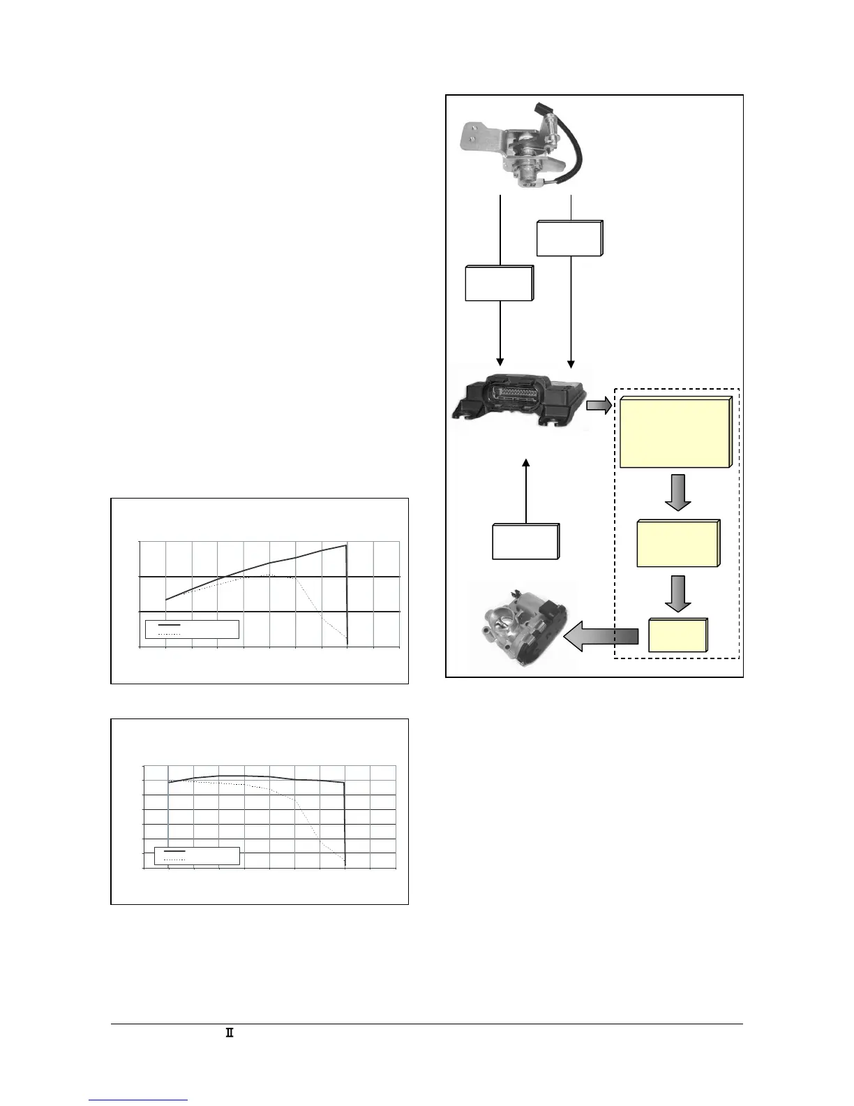
(Figure 30) describes the signal flow process of the
MI-04 DBW section. The Acceleration Pedal
assembly uses two potentiometers to detect pedal
position. These two signals, accelerator pedal
position 1 (APP1) and accelerator pedal position 2
(APP2) are sent directly to the SECM. The SECM
uses a series of algorithms to self calibrate and cross
check the signals from the pedal assembly. A demand
position for the throttle will then be derived and sent
to the throttle as a throttle position sensor demand
(TPSd). The signal will be processed through a PID
(Proportional, Integral, Derivative) controller in the
SECM to achieve the appropriate motor-current
response then passed to the throttle. The throttle
moves to the commanded position and provides a
feedback signal from the throttle position sensor
(TPS) to the SECM.
TPS
DBW
Throttle
SECM
Acceleration
Pedal
APP2
APP1
5msec
Update
Rate
APP 0-100%
•Self Calibration
• Cross Check of
APP1 & APP2
TPSd
(Demand)
PID
Figure 30
SystemPowerComparison
0.0
20.0
40.0
60.0
1000 1200 1400 1600 1800 2000 2200 2400 2600 2800 3000
RPM
Power,hp(corrected)
Baselinesystem
MI-4 System
SystemTorqueComparison
0.0
20.0
40.0
60.0
80.0
10 0 . 0
12 0 . 0
14 0 . 0
1000 1 200 1 400 1600 1800 2000 2200 2400 2600 2800 3000
RPM
Torque,ft-lb(corrected)
Baselinesystem
MI-4 System
 Loading...