TAPE SECTION
Test Tape be used
HEAD ADJUSTMENT (AZIMUTH)
1. 10KHz test tape(example: MTT-114N) must be used for this adjustment.
2. Connect to VTVM or oscilloscope to the headphone jack or speaker terminal.
3. Press the play button.
4. Adjust the azimuth by using a screw driver to maintain the max. L&R output voltage.
5. Adjust tape respectively, Please secure the azimuth position by using locking paint.
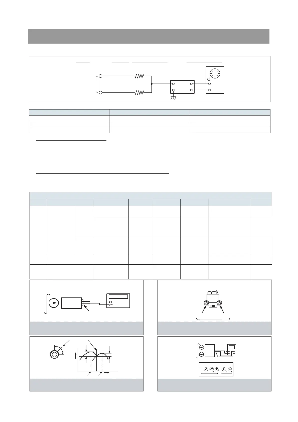
RECORDING BIAS OSCILLATOR FREQUENCY ADJUSTMENT
1. Connect the frequency counter to TP603, GND.
2. Press the REC button.
3. Adjust L603 to obtain 80 KHz
±
500Hz
Tape Contents Use
MTT-111N 3 KHz Tape Speed Adjustment
MTT-114N 10 KHz Head Azimuth Adjustment
MTT-5511 Blank Record Frequency Property
VTVM
Scope
R-CH
L-CH
47 kohm
47 kohm
Input Level
Measurement
Point
Input Point
Output Level
Measurement
Point
TAPE ALIGNMENT CHART
Step Item Reference Value Test Tape Adjust Point Test Point Note FIG.
1
Tape Speed
Adjustment
Normal
3,015~3,025Hz MTT-111N
Line Out L/R
Channel
Confirm Wow & Flut-
ter is within 0.35%
FIG.1
3,000~3,010Hz MTT-111N
Line Out L/R
Channel
Confirm Tape Speed
of end position after
adjustment at tape
start position
FIG.1
2
Azimuth Adjustment
Maximum Level
Phase:Within90∞
MTT-114N Head Screw
Line Out L/R
Channel
FIG.2,3,4
3
Recording Bias Oscilla-
tor Frequency Adjust-
ment
80 KHz
±0.5
MTT-5511 L603
TP603,GND
Adjust with frequency
counter connected.
FIG.1
FIG. 1 : Tape Speed & Record Bias Oscillator
Frequency Adjust Circuit
Test Tape : MTT-111N(3kHz)
MTT-5511(Blank)
Frequency Counter
Output Level
Measurement Point
Set
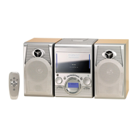
FIG. 2 : Tape Azimuth Adjust Location
(Record/Playback Head)
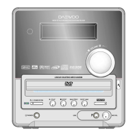
FIG. 3 : Tape Azimuth Adjust Head Screw & Waveform
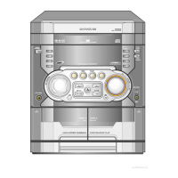
FIG. 4 : Tape Azimuth Adjust Circuit & Waveform
Forward
Side
Reverse
Side
Adjust with Frequency
Counter Connected
L-CH
Peak
R-CH
Peak
Screw
Angle
Output Level
within
1 dB
within
1 dB
L-CH
Peak
R-CH
Peak
Screw Angle
VH
Oscilloscope
L-CH
Output Level
Measurement Point
Set
Test Tape
MTT-114N
(10kHz)
Screen Pattern
In Phase 45 90 135 180
Good Wrong