This document serves as a Quick Start Guide for a Network Video Recorder (NVR), providing essential information for its installation, initial setup, and basic operation. It is designed to be a reference tool for users and should be kept for future consultation.
The NVR's primary function is to record and manage video streams from network cameras. It supports various configurations and offers features for device initialization, camera registration, schedule management, video playback, and remote access via web and mobile applications.
Important Safeguards and Warnings:
- Electrical Safety: All installation and operation procedures must comply with local electrical safety codes. The device requires a CLASS I construction connection with protective earthing. It should be powered by a SELV (Safety Extra Low Voltage) compliant power supply, meeting IEC 60950-1 standards. Proper grounding is crucial to mitigate electric shock risks. The manufacturer disclaims liability for fires or electric shocks resulting from improper handling or installation.
- Transportation Security: The NVR should be handled with care during transportation, storage, and installation, avoiding heavy stress, violent vibrations, or water splashes.
- Installation: The device should be kept upright and handled carefully. Power should not be applied until installation is complete, and no objects should be placed on the NVR.
- Qualified Engineers: All examination and repair work must be performed by qualified service engineers. Unauthorized modifications or repair attempts will void liability.
- Environment: The NVR must be installed in a cool, dry place, away from direct sunlight, flammable, or explosive substances. It is designed for specific operating environments, particularly for ITE (Information Technology Equipment) that is not likely to require connection to an Ethernet network with outside plant routing. If connected to PoE networks, it must not be routed to the outside plant.
- Accessories: Only manufacturer-recommended accessories should be used. Before installation, users should verify that all components are included in the package. Any missing or damaged items should be reported to the local retailer immediately.
- Lithium Battery: Improper battery use can lead to fire, explosion, or personal injury. When replacing the battery, ensure the same model is used.
Preparation Work:
Before installation, users should check the entire package for visible damage or accidental clashes during transportation. The model on the front panel and the label on the rear panel should be verified against the purchase order and checked for cleanliness. The label, containing the serial number, is important for after-sales service and should not be torn off or discarded. Internally, the data cable, power cable, fan cable, and main board should be inspected for damage and secure connections. If any connections are loose, the local retailer or service engineer should be contacted.
HDD Installation:
- SMART BOX: This series supports one 2.5-inch SATA HDD. To install, first draw out the HDD bracket. Ensure the metal surface of the HDD faces up, then insert the HDD horizontally into the bracket until the columns on the sides secure it. Finally, insert the bracket with the HDD into the device. To remove, pull the spring up and then remove the HDD.
- SMART 1U, MINI 1U, COMPACT 1U, 1U: For these models, users should first check if an HDD is already installed. The manual recommends using HDDs of 7200rpm or higher, and PC HDDs are generally not recommended.
- Installation Steps:
- Loosen the screws on the bottom of the chassis.
- Place the HDD according to the four holes in the bottom.
- Turn the device upside down and firmly secure the screws.
- Connect the HDD data and power cables to the HDD and the mainboard.
- Replace the cover and fix the screws on the rear panel.
- For MINI 1U, COMPACT 1U, 1U (alternative steps):
- Loosen the screws of the upper cover and side panel.
- Connect one end of the HDD data cable and power cable to the mainboard.
- Connect the other end of the HDD data cable and power cable to the HDD.
- Place the HDD in accordance with the four holes on the bottom of the chassis.
- Turn the device upside down; fix the screws to secure the HDD on the bottom of the chassis.
- Put the cover in accordance with the clip and then fix the screws on the rear panel and side panel.
Rear Panel:
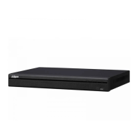
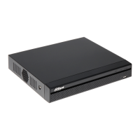
The rear panel configurations vary by product series.
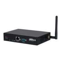
- SMART BOX: Features PoE ports for network cameras, Ethernet port, power input port, USB port, HDMI port, and VGA port.
- SMART 1U: Includes USB port, audio talk input/output port, audio output port, GND, HDMI port, VGA port, Ethernet port, and power input port.
- MINI 1U, COMPACT 1U: Provides USB port, Ethernet port, power input port, HDMI port, VGA port, and GND.
- 1U Series: Offers power input port, power on/off button, VGA port, Ethernet port, audio output port, RS232 port, alarm input/output port, GND, PoE ports for network cameras, audio talk input/output port, HDMI port, and USB port.
Users should check the power input icon on the rear panel:
DC 12V indicates DC 12V power input.DC 48V indicates DC 48V power input.
The 4PoE series supports 48V 50W total power, while the 8PoE series supports 48V 120W total power.
GUI Operation:
- Boot Up:
- Connect the NVR to the power adapter, then to the power socket.
- Ensure the rated input voltage matches the device and the power wire connection is secure.
- Click the power on/off button (front or rear panel).
- Connect the device to a monitor and a mouse.
- After booting, the system defaults to multiple-channel display mode.
- Safety Note: Always use a stable current; a UPS is recommended if necessary.
- Device Initialization: For first-time use, set a login password for the default
admin user.
- The device displays the initialization interface.
- Set the login password for
admin:
- Password must be 8 to 32 digits, containing letters, numbers, and special characters (excluding
"", '', ,, ..., &). It must include at least two types of characters. A strong password is recommended.
- Optionally, set a prompt question to help remind the password on the login interface.
- Click
Next to proceed to the unlock pattern interface.
- Safety Note: Keep the
admin password secure and change it regularly.
- Unlock Pattern:
- Set an unlock pattern.
- After setting, the device moves to the password protection interface.
- Note: The device defaults to unlock pattern login if set. Otherwise, the password must be entered. Users can
Skip this step if an unlock pattern is not desired.
- Security Questions:
- Set security questions and corresponding answers, or input an email address for password reset.
- These can be used to reset the
admin password if forgotten.
- Users can
Cancel the email or security questions box and click Next to skip this step.
- Note: For password reset via security questions, access the local menu interface.
- Completion: Click
OK to complete initialization. The device will then go to the startup wizard interface.
- Change IP Address:
- Navigate to
Main menu -> Setting -> Network -> TCP/IP.
- The default IP address is 192.168.1.108.
- Note: Different products may have varying Ethernet adapter types and quantities.
- Camera Registration:
- Go to
Main menu -> Setting -> Camera -> Registration, or right-click on the preview interface and select Camera Registration.
- Click
Device search.
- Double-click the desired device from the list, or check the box next to its name and click
Add.
- Click
OK to complete the addition.
- Schedule:
- Access
Main menu -> Setting -> Storage -> Schedule.
- By default, all channels record continuously after boot-up. Users can customize the record period and type.
- Playback:
- Go to
Main menu -> Search, or right-click on the preview interface and select Search.
- This interface allows searching and playing back video record files or images.
- Shut Down:
- Navigate to
Main menu -> Shut down.
- Click
Shut down.
Web Operation:
For first-time web login, the device must be initialized first.
- Login:
- Open a browser and enter the NVR's address in the address bar, then press
Enter.
- The login interface will appear.
- Input the username (
admin by default) and the password set during initialization.
- Safety Note: Change the
admin password regularly. If forgotten, use the Forgot password option.
- Click
Login.
- The preview interface will appear.
- Note: If it's the first time logging in via web, install the required plug-in.
P2P (Peer-to-Peer) Access:
- Step 1: Download APP:
- Scan the client QR code (found on the device package box or via
Main menu -> Setting -> Network -> P2P on the local menu, or Setup -> Network -> TCP/IP -> P2P on the web interface) to download the mobile application.
- Step 2: Add Device:
- After installation, run the APP and select
Live preview.
- Tap the menu icon (usually three horizontal lines) and then tap
Device Manager.
- Tap
P2P to add the device.
- Scan the device label or the device SN (found on the device local menu) to add the device.
- After scanning, the product SN will be displayed. Click
Start live preview to view live video on the cell phone.
General Notes:
- Slight differences may exist in the user interface across different versions.
- All designs and software are subject to change without prior written notice.
- All trademarks and registered trademarks belong to their respective owners.
- For any uncertainties or controversies, refer to the final explanation provided by the manufacturer.
- For more detailed information, visit the manufacturer's website or contact a local service engineer.