Do you have a question about the Dahua PFH610V-IR and is the answer not in the manual?
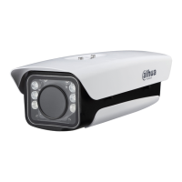
This document describes the Light-duty Protective Housing, a device designed to provide all-weather protection for cameras and lenses, ensuring their normal operation in severe environmental conditions such as high temperatures, low temperatures, rain, and snow. The housing supports the installation of cameras and lenses of various sizes and features a built-in adjustable camera fixing plate, offering a relatively high level of protection.
The primary function of the Light-duty Protective Housing is to safeguard cameras and their lenses from harsh environmental elements. It achieves this through a fully sealed aluminum shell, which provides an IP66/IP67 protection level, indicating strong resistance to dust and water ingress. For models with specific features, the housing also incorporates a built-in heating and cooling system to maintain stable operating temperatures for the camera, preventing performance degradation due to extreme heat or cold. The windows of the housing are equipped with waterproof films to minimize the impact of weather conditions on the camera's view.
Certain models of the housing include infrared (IR) ray or white light illumination capabilities, providing auxiliary light for improved visibility in low-light conditions. These illuminators can offer a range of 1 to 100 meters for infrared light and up to 60 meters for white light, depending on the specific model. The housing also supports remote control functionalities for its LED illuminators and windshield wiper, allowing for flexible operation and maintenance without direct physical access.
The control and wiring instructions for the housing vary based on the type of camera it accommodates (IPC or CVI) and the desired control mode. There are three main control modes: Remote 1, Remote 2, and Routine.
In Remote Mode 1, the LED and wiper status can be controlled via a WEB interface. This mode is typically used with cameras that have RS485 control functions, allowing for integrated management of the housing's features alongside the camera's settings. The wiring diagram for this mode shows connections for external washer, wiper, LED, 485 (A/B), and camera power (AC24V), along with audio and video output interfaces on the camera.
Remote Mode 2 is designed for cameras without RS485 control functions, where the camera's "N/C" interface can be used for "LED" and "WIPER" connections. In this mode, the LED and wiper switch can be controlled through the camera's alarm option. This allows the camera to trigger the housing's functions based on predefined alarm events. The wiring for this mode also includes connections for washer, wiper, LED, 485, and camera power, with the camera's alarm output controlling the housing's features.
The Routine Mode is for cameras without RS485 control functions, particularly when the camera's "N/C" interface cannot simultaneously satisfy "LED" and "WIPER" connections. In this mode, the wiper switch is controlled through the camera's alarm, while the LED switch is managed by an LED photosensitive unit. This provides an automated control mechanism for the LED based on ambient light conditions, and manual or event-based control for the wiper via the camera's alarm output.
For CVI cameras, similar Remote 1 and Routine modes are available. In CVI Remote Mode 1, LED and wiper status are controlled via the WEB interface, utilizing the camera's RS485 control function. In CVI Routine Mode, the wiper switch is controlled by the camera's alarm, and the LED switch by a photosensitive unit, for cameras without RS485 control.
The housing is designed for ease of installation and debugging. A brand-new side cover design facilitates access to internal components, simplifying the setup process. The housing can be opened and locked using two M6 screws and an internal hexagonal wrench (5.0mm). Before closing the cover, it is crucial to ensure that the waterproof ring of the shell is correctly installed to maintain the housing's waterproof performance.
Camera installation involves several steps: first, removing the camera installation plate from the housing; second, fixing the camera onto this plate; and finally, fixing the camera installation plate back into the housing shell. When installing the camera lens, it is recommended to position it close to the inner surface of the glass (1-3mm away) to avoid affecting the viewing angle. Depending on the camera size, the installation plate can be mounted on either the obverse or reverse side.
For models with IR lamp panels, a dial switch is provided for controlling the IR lamps. By default, 6 IR lamps are turned on. In modes other than Remote Mode 1, the dial switch can be adjusted to turn off up to 4 lamps, allowing for short-distance fill-in light requirements.
The housing supports various installation methods through different bracket models. A general bracket with threaded holes (M6) can be used for standard installations. For concealed wiring, a special bracket integrates the housing and bracket, allowing the wiring harness to pass through the bracket. This involves guiding the wiring harness through the bracket, fastening the bracket to the housing, and then securing a waterproof joint onto the wiring harness. During wiring, it is advised to separate signal and power harnesses and route them through different holes with waterproof joints. If only one hole is used, the other should be sealed with a waterproof plug to prevent water leakage.
The design of the housing, particularly the side cover, simplifies access for maintenance and debugging. The robust construction with an aluminum shell and IP66/IP67 protection level ensures durability and reduces the need for frequent repairs due to environmental damage. The built-in heating and cooling systems in certain models contribute to the camera's longevity by preventing operation outside optimal temperature ranges.
The remote control capabilities for LED and wiper functions allow for operational adjustments and troubleshooting without requiring physical access to the housing, which is particularly beneficial for installations in hard-to-reach locations. The modular design, where the camera is fixed onto an installation plate, also facilitates easier camera replacement or maintenance.
The document emphasizes the importance of proper installation of the waterproof ring and waterproof joints to maintain the housing's protective integrity, which is a key aspect of its long-term maintenance. The availability of different bracket models ensures compatibility with various installation scenarios, contributing to the overall adaptability and maintainability of the system.
It is important to note that the bracket is not included in the basic configuration of the housing and must be purchased separately if needed. For anti-corrosion protective housings, a specific anti-corrosion bracket must be used to maintain the system's integrity in corrosive environments. The company reserves the right to revise document information and product functions, with updates to be included in new versions without prior announcement, ensuring that users always have access to the most current information for maintenance and operation.
| Model | PFH610V-IR |
|---|---|
| Category | Camera Accessories |
| Type | IR Illuminator |
| Material | Aluminum |
| Wavelength | 850 nm |
| Ingress Protection | IP66 |
| Weatherproof | Yes |
| Infrared (IR) Cut Filter | No |
| Operating Temperature | -30 °C to +60 °C |
| Humidity | 10%–90% RH |
| Applicable Model | Dahua Cameras |