EasyManua.ls Logo

Daihen CPVE-400 User Manual

Daihen CPVE-400
87 pages
To Next Page IconTo Next Page
Page #1 background imageLoading...
Page #1 background image
2P30161-4
OWNER'S MANUAL
FOR
DIGITAL INVERTER
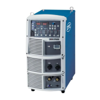
CPVE-400/500
MODEL: CPVE-400 P30161/C1017
CPVE-500 P30162/C1018
INVERTER CONTROLLED WELDING POWER SOURCE
DO NOT DESTROY
IMPORTANT: Read and understand the entire contents of this
manual, with special emphasis on the safety material throughout
the manual, before installing, operating, or maintaining this
equipment. This equipment and this manual are for use only by
persons trained and experienced in the safety operation of
welding equipment. Do not allow untrained persons to install,
operate or maintain this equipment. Contact your distributor if you
do not fully understand this manual.
DAIHEN Corporation
WELDING PRODUCTS DIVISION
Upon contact, advise MODEL and MANUAL NO.

Wminfo

Questions and Answers:

Daihen CPVE-400 Specifications

General IconGeneral
BrandDaihen
ModelCPVE-400
CategoryInverter
LanguageEnglish

Summary

General Safety Information

Arc Welding Safety Precautions

Detailed safety precautions for arc welding, covering electric shock, burns, and fumes.

General Operation Notices

Understanding Rated Duty Cycle

Explanation of rated duty cycle and its impact on machine performance and longevity.

Static External Characteristics

Description of the welding power source's constant voltage external characteristics.

Wire Feeder Combinations

Information on connecting different wire feeders and necessary settings.

Gas Ratio & Wire Extension Effects

Impact of gas mixture ratio and wire extension on welding performance.

Standard Configuration & Accessories

Standard Configuration Details

Description of the standard equipment composition for MAG/MIG welding.

List of Standard Accessories

List of standard accessories provided with the welding machine for checking.

User-Supplied Items

List of essential items the user needs to prepare before operation, such as gas and wire.

Component Identification

Welding Power Source Parts

Detailed labeling of components on the welding power source unit.

Power Source Equipment Requirements

Commercial Power Supply Specs

Specifications for commercial power supply, including voltage and capacity.

Engine Generator Power Precautions

Cautions for using engine generators as a power source for the welding machine.

Transport & Installation Guide

Safe Transport Procedures

Guidelines for safe carrying and hoisting of the welding power source to prevent accidents.

Installation Safety Guidelines

Instructions for installing the welding machine, considering fire hazards and gas fumes.

Connection & Grounding for Safety

Input Voltage Selection

Instructions on how to select and switch the input voltage for the welding power source.

Output Side Cable Connection

Procedures for connecting cables to the output terminals of the welding power source.

MAG/MIG Welding Connection

Step-by-step connection procedure for MAG/MIG welding applications.

DC STICK Welding Connection

Step-by-step connection procedure for DC STICK welding applications.

Gas Hose Connection

Instructions for safely connecting the gas hose and regulator to the gas cylinder.

Input Power Grounding

Procedures for grounding the welding power source and connecting the input power.

Welding Preparation Steps

Personal Protective Equipment (PPE)

Guidelines for selecting and using appropriate personal protective equipment (PPE) for welding.

Gas Regulator & Switch Operations

Operating the control switches and adjusting the gas regulator for welding.

Wire Feeder Inching Operation

Instructions for the inching operation, used for feeding wire.

Troubleshooting Welding Conditions

Information on potential welding troubles caused by improper conditions and their remedies.

CO2 Welding Conditions (Fillet/Groove)

Example welding conditions for horizontal fillet and down fillet welds using CO2 gas.

CO2 Welding Conditions (Butt/Groove)

Example welding conditions for I Shape Butt and Single/Double Grooves.

CO2 Welding Conditions (Lap Fillet)

Example welding conditions for Lap Fillet welds using CO2 gas.

CO2 Flux-Cored Wire Conditions

Example welding conditions for CO2 welding using flux-cored wires.

MAG Short Arc Welding Conditions

Example welding conditions for MAG short arc welding with specified gas mixture.

Operating the Welding Machine

Operation Panel Overview

Identification and explanation of the controls and indicators on the operation panel.

Basic Welding Settings

Steps for basic setting of welding conditions using gas, wire type, and diameter keys.

Setting Welding Mode & Conditions

Guide to setting welding modes based on gas, wire type, and diameter selection.

Adjusting Welding Parameters

How to set welding parameters like current, voltage, and display modes.

Crater Fill Function Settings

Explanation and operation of crater fill functions for weld termination.

Arc Spot Welding Procedure

How to perform arc spot welding, including setting spot time.

Welding Voltage Adjustment Methods

Methods for adjusting welding voltage (individual, synergic).

Arc Characteristics Adjustment

How to adjust arc characteristics for optimal welding results.

Gas Check Function

Using the gas check function to verify gas flow.

Wire Feed Inching Function

How to use the inching function for wire feeding.

Parameter Adjusting Knob Usage

Guidance on using parameter adjusting knobs for welding adjustments.

Verifying Parameters on Display

How to check and interpret parameter settings and welding results on the display.

Analog Remote Control Operation

Instructions for operating the welding power source using the analog remote control.

Advanced Settings: Internal Functions

Explanation of various built-in internal functions for advanced settings.

Internal Function Setup Guide

Table and guide for setting internal functions (F1-F20).

Internal Function Details (F4, F5)

Details on specific internal functions like F4 (Auto/Semi-auto Mode) and F5 (External voltage range).

Internal Function Details (F6, F7)

Details on internal functions F6 (up-slope time) and F7 (down-slope time).

Internal Function Details (F8-F12)

Details on internal functions F8 (result display time), F9 (no function), F10 (Power Saving), F11 (JOB MEMORY adjustment), F12 (soft arc mode).

Internal Function Details (F13-F17)

Details on internal functions F13 (Penetration Control), F14 (Wire feeder selection), F15 (INITIAL Condition), F16 (Gas Pre-flow), F17 (Gas Post-flow).

Key Lock Function

How to activate and deactivate the key lock function to prevent accidental changes.

Password Lock Setup

Setting up and managing a password lock for enhanced security.

JOB MEMORY: Storing Conditions

Storing and recalling welding conditions using the JOB MEMORY function.

Deleting Stored Welding Conditions

Procedure for deleting stored welding conditions from memory, individually or all.

Resetting to Initial Values

Restoring welding conditions and internal functions to their initial factory values.

Checking Software Version

How to check the installed software version of the welding power source.

Applied Functions & Connections

External Connection Terminal Block

Details on the internal terminal block for external connections and safety precautions.

10-Pin Terminal Block Signals

Description of signals and their functions for the 10-pin terminal block.

Automatic Machine Integration

How to connect the welding power source with an automatic welding machine.

Cooling Blower Auto-Stop

Explanation of the auto-stop function for the cooling blower.

Optional Accessories Overview

Information on optional accessories like extension cables and gas tubes.

Extension Cables & Gas Tubes

Details on selecting and using extension cables and extended gas tubes.

MAG Flow Meter Precautions

Specific precautions for using a MAG gas flow meter.

Wire Feeder Selection

Information on wire feeder models and their corresponding internal function settings.

Wire Feeding Roll Selection

Precautions for wire feeding rolls to ensure welding performance.

Argon Gas Flow Meter Usage

Warnings and precautions for using argon gas flow meters.

Maintenance & Troubleshooting

General Maintenance Precautions

Important safety warnings and precautions to be observed during maintenance.

Routine Power Source Maintenance

Daily and periodic checks to ensure the safety and efficiency of the welding power source.

PCB Replacement Precautions

Safety precautions and procedures for replacing printed circuit boards.

Insulation & Voltage Tests

Procedures for performing insulation resistance and voltage withstand tests.

Troubleshooting Error Codes

Guidance on how to identify and resolve error codes displayed by the welding machine.

Troubleshooting Common Issues

A table listing common troubles, their causes, and solutions.

Electrical Schematic Diagram

Electrical schematic diagram of the welding power source for reference.

Internal Parts Layout Diagrams

Diagrams showing the layout of internal parts of the welding power source.

Parts List & Identification

Power Source Parts List

Detailed listing of power source components and quantities for CPVE-400 and CPVE-500.

Technical Specifications

CPVE-400/500 Specifications

Detailed technical data including voltage, current, duty cycle, and environmental ratings.

External Dimensions & Views

Diagrams illustrating the external dimensions and views of the welding power source.

Parameter Initial Values & Ranges

Table of initial parameter values and their adjustable setting ranges for functions.

JOB MEMORY: Storing & Loading

Procedures for saving and loading welding conditions into JOB MEMORY.

Internal Function Setup Procedure

Steps to enter and set internal functions using the DISPLAY CHANGE key.

Service & Support Information

Contacting Dealer for Service

Details to provide when contacting a dealer for service, including model and serial number.

Related product manuals