EasyManua.ls Logo

Daihen WB-M500 - User Manual

Daihen WB-M500
145 pages
Print Icon
To Next Page IconTo Next Page
Loading...
E n s u r e t o r e a d t h i s
i n s t r u c t i o n m a n u a l
thoroughly for safe and
proper use of the product.
October, 2013
Manual No. : 1P30135-1
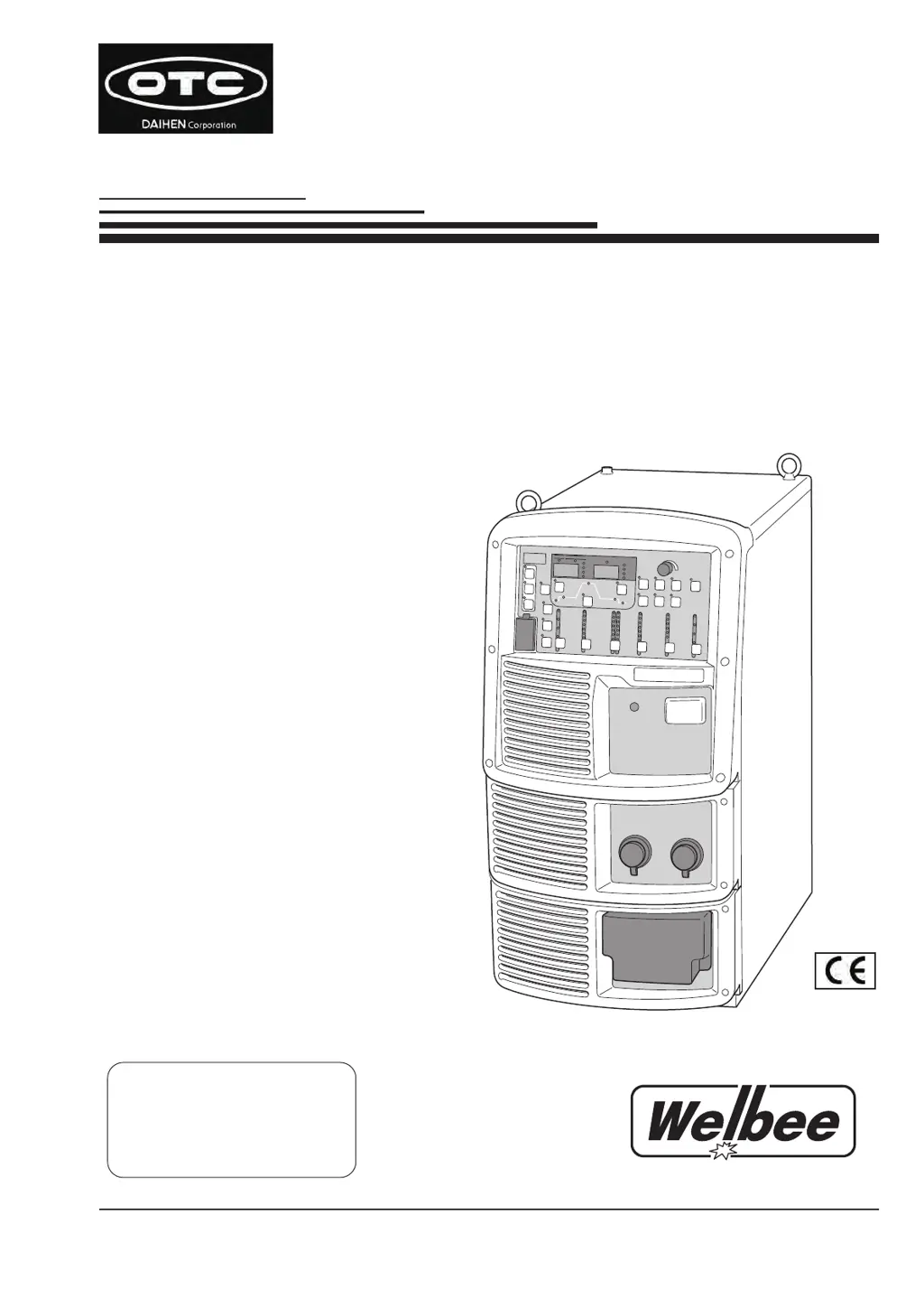
Model: WB-M500
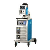
Welbee Inverter
M500
OWNER'S MANUAL
CO
/MAG
Welding power source
2
DAIHEN Corporation

Table of Contents

Questions and Answers

  • A
    Angel CainAug 19, 2025
    What to do if shielding gas is not flowing in my Daihen WB-M500?
    • C
      Christopher SantosAug 19, 2025
      If the shielding gas isn't flowing, there could be several reasons: * The gas cylinder valve might be closed. Make sure to open it. * The gas cylinder pressure could be too low. Replace the cylinder. * The external input settings might be incorrect. Check the settings of internal functions F29 to F32. * The external input cables might be disconnected or short-circuited. Inspect the cables connected to the external input terminal block and repair or replace them if necessary.
  • M
    Melanie PageAug 21, 2025
    Why is the arc unstable on my Daihen WB-M500?
    • S
      smaldonadoAug 21, 2025
      An unstable arc can occur due to several factors: * Incorrect welding mode settings. Verify the settings for wire diameter, wire materials, and shielding gas. * Defective wire or wire feeding issues. Inspect the wire and wire feeder for any problems. * Incorrect voltage detection cable connection. Ensure the voltage detection cable is properly connected. * Noise in the voltage detection cable. Try adjusting the arc characteristics to the plus side.
  • S
    stacey83Aug 23, 2025
    What to do if shielding gas does not stop flowing in my Daihen WB-M500 Inverter?
    • S
      Stephanie ThompsonAug 23, 2025
      If the shielding gas continues to flow, it might be due to: * Incorrect external input settings. Verify the settings of internal functions F29 to F32. * Disconnected or short-circuited external input cables. Inspect the cables connected to the external input terminal block and repair or replace them if necessary.
  • T
    Thomas Hill DDSAug 26, 2025
    How to fix Daihen WB-M500 when wire is not fed (no error code)?
    • S
      Scott RamseyAug 26, 2025
      If the wire isn't feeding and no error code appears, consider these possibilities: * The pressure roll of the wire feeder might have come off. Correctly set the pressure roll of the wire feeder. * There could be an issue with the wire feeder cables. Check the cables for any abnormalities.
  • R
    Regina WolfeAug 27, 2025
    What to do if I can't set the current/voltage on my Daihen Inverter?
    • J
      John GloverAug 28, 2025
      If you're unable to set the current or voltage, it could be due to: * The automatic machine mode being selected. Check that the setting of internal functions F4 is correct. * An analog remote control being connected. When an analog remote control is connected, its settings take priority. * A broken encoder. The printed circuit board PCB2 (P30086R00) needs to be replaced. Contact your dealer.
  • D
    Darren GarnerAug 30, 2025
    What causes blowholes when using a Daihen WB-M500?
    • A
      Anthony PetersonAug 30, 2025
      Blowholes can be caused by: * A problem with the shielding gas. Check the gas cylinder and hose for any issues. * A worn-out welding torch tip. Replace the chip.
  • N
    Nicole RileySep 1, 2025
    What to do if arc does not generate even when the setting of welding conditions is correct on my Daihen Inverter?
    • L
      Linda JohnsonSep 1, 2025
      If the arc doesn't generate despite correct welding condition settings, check these: * A loose torch cable connection. Ensure the torch cable is securely connected. * A broken torch switch. Verify that the torch switch is functioning correctly.
  • H
    Heidi SnyderSep 3, 2025
    Why doesn't the mode change when I press the CRATER-FILL key on my Daihen Inverter?
    • B
      bcarterSep 3, 2025
      If the mode doesn't change when pressing the CRATER-FILL key, it might be because the internal function F4, F48 or F51 is set to "ON". Turn the settings to "OFF".
  • H
    Heather WashingtonSep 5, 2025
    What to do if the power LED switch does not light even when the power switch is turned on on Daihen Inverter?
    • J
      Joanne CarterSep 5, 2025
      If the power LED switch doesn't light up when the power switch is on, the primary power source might not be supplied. Ensure the primary power source is between 340 to 460 V.
  • M
    matthewbartonSep 7, 2025
    What does it mean when the "Temperature WARNING" LED lights on my Daihen WB-M500?
    • J
      Jason MaldonadoSep 7, 2025
      If the "Temperature WARNING" LED lights up and an error code is displayed, the protection circuit has been activated due to a temperature error. Leave the Inverter untouched (with the power on) and let the cooling fan run for at least 10 minutes, then turn off the power. Afterward, clean any dust inside the welding power source.

Summary

Important Information

Product Usage and Safety Guidelines

Defines intended use, safety measures, and operational restrictions for the welding power source.

Copyright and Export Regulations

Outlines copyright ownership and conditions for exporting the product outside the country.

Product Disposal Instructions

Provides guidance on proper disposal of welding equipment in compliance with regulations.

Service and Support

Contacting Service Personnel

Information required when contacting dealers for service, including product details.

Chapter 1 Safety Information

Warning Symbols and Safety Precautions

Explains hazard symbols and general safety measures for operating the welding power source.

Operating Precautions

Safety measures for operating the welding power source and welding machine.

Power Supply and Electric Shock Precautions

Safety measures to prevent electric shock or burn injury during operation.

Air Discharge and Respiratory Protection

Precautions for suffocation, gas poisoning, and fume exposure during welding.

Flammable Materials Precautions

Safety measures to prevent fire, explosion, and rupture near flammable materials.

Gas Cylinder and Regulator Precautions

Safety measures to prevent gas cylinder explosion and accidents caused by gas.

Plastic Parts Handling Precautions

Precautions to prevent electric shock or fire from damage to plastic parts.

Disassembly and Modification Precautions

Safety measures to prevent electrical shock, fire, or malfunction from disassembly.

Protective Equipment Precautions

Measures for protection from arc ray, spatter, and noise during welding.

Rotating Part Precautions

Safety measures to prevent being caught or pinched by rotating parts.

Principal Safety Standards

Lists relevant safety standards for arc welding equipment installation and use.

Chapter 2 Product Specification and Configuration

Specifications Overview

Details technical specifications including voltage, current, dimensions, and mass.

Applicable Welding Methods

Outlines compatible welding methods, wire types, diameters, and travel speeds.

External Dimensions

Shows the physical dimensions of the welding power source with illustrations.

Rated Duty Cycle

Explains the rated duty cycle of the welding power source and its operational limits.

Product Configuration

Outlines the standard composition and optional accessories for the welding power source.

Part Names

Identifies and illustrates the components on the front and rear panels of the unit.

Chapter 3 Transportation and Installation

Required Equipment and Environment

Lists necessary power supply equipment and suitable installation environment criteria.

Transportation Procedures

Details steps and precautions for safely transporting the welding power source.

Chapter 4 Connection

Connection and Grounding Precautions

Essential safety measures for connecting and grounding the welding power source.

Connecting Power Source Components

Step-by-step guide for connecting output cables, wire feeder, torch, and shielding gas.

Input Power and Grounding

Instructions for proper grounding and connecting the input power supply.

External Equipment and Robot Connection

How to connect external equipment, including robots and automatic machines.

Voltage Detection Cable Wiring

Details on wiring the voltage detection cable at the base metal side.

Chapter 5 Welding Operation

Welding Operation Safety Precautions

Safety measures for welding, including respiratory protection and environmental hazards.

Pre-Welding Checks and Setup

Essential checks, power-on, and gas supply procedures before welding.

Welding Process Steps

Wire inching, condition setting, performing welding, and ending the operation.

Chapter 6 Welding Condition

Welding Conditions Overview

Lists settable parameters, functions, and internal functions for welding conditions.

Operation Panel Controls

Explanation of the displays and keys on the welding power source operation panel.

Setting Welding Conditions

Detailed steps for setting welding modes, parameters, and sequences.

Internal Function Configuration

How to configure and customize internal functions for specific applications.

Analog Remote Control Operation

Instructions for operating the optional analog remote control.

Chapter 7 Administrator Functions

Welding Condition Protection

How to set passwords and prevent erroneous operation of the panel.

Welding Result Control Function

Manages welding results like points, consumption, time, and alarm settings.

Data Backup and Import

Procedures for backing up and importing data via USB flash drive.

Initializing Settings

Resets welding conditions and internal functions to their default settings.

Software Version Check

How to check the installed software version of the welding power source.

Chapter 8 Maintenance and Inspection

Maintenance and Inspection Safety

Safety guidelines and precautions for performing maintenance and inspection tasks.

Daily and Periodical Inspections

Procedures for routine daily checks and periodic inspections every 3-6 months.

Replacement Parts and Testing

Identifies parts requiring periodic replacement and testing procedures.

Chapter 9 Troubleshooting

Error Code Resolution

How to identify and resolve errors indicated by LEDs and error codes on the panel.

Common Problem Solving

Addresses common issues not related to error codes, with causes and corrective actions.

Chapter 10 Reference Materials

Parts List and Drawings

Lists all parts with codes and specifications, includes schematic and layout drawings.

Welding Condition Settings Guide

Provides guidance and examples for setting welding conditions based on material and joint.

Daihen WB-M500 Specifications

General IconGeneral
BrandDaihen
ModelWB-M500
CategoryInverter
LanguageEnglish

Related product manuals