Do you have a question about the Daihen OTC WB-M400 and is the answer not in the manual?
Provides essential instructions for safe operation and handling of the product.
Information on how to contact dealers for service and required information.
Explains the meaning and usage of safety warning symbols in the manual.
Details general safety precautions for operating the welding power source.
Lists relevant safety standards and regulations for arc welding equipment.
Details the specifications and external dimensions of the welding power source.
Explains applicable welding methods, gas types, and wire diameters.
Shows the external dimensions of the welding power source with diagrams.
Explains the rated duty cycle of the welding power source and its implications.
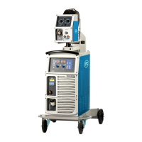
Explains the standard and optional composition of the welding power source.
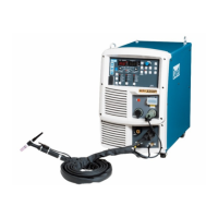
Details the standard components included with the welding power source for different welding types.
Explains the accessories supplied with the welding power source.
Lists accessories that need to be prepared by the customer.
Lists optional accessories available for the welding power source.
Provides details on optional extension cables and hoses for extending working radius.
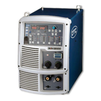
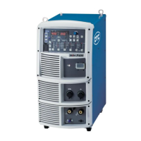
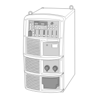
Explains the names of the parts on the front and rear panels of the welding power source.
Identifies and describes the components on the front panel.
Identifies and describes the components on the rear panel.
Details necessary power supply equipment and protective devices for installation.
Specifies the required supply voltage and installed capacity for the welding power source.
Provides precautions when using engine generators or auxiliary power.
Explains the need for ventilation and partial exhaust facilities in welding work areas.
Details requirements for ventilation equipment to ensure oxygen concentration.
Explains the use of partial exhaust facilities to prevent health damage from fumes.
Explains the required environmental conditions for installing the welding power source.
Details safe installation locations considering factors like combustibles, chemicals, and ambient conditions.
Discusses potential electromagnetic interference and methods to reduce it.
Outlines the procedures and precautions for transporting the welding power source.
Explains the procedure for safely transporting the welding power source using lifting lugs.
Provides essential safety precautions for connecting and grounding the welding power source.
Details the step-by-step procedure for connecting the welding power source.
Explains how to connect the power cables to the output terminals.
Details the procedure for connecting the wire feeder.
Explains how to connect the welding torch.
Describes the specific connection procedure for TIG welding.
Describes the specific connection procedure for DC STICK welding.
Explains the procedure for connecting the shielding gas system.
Details the grounding work and input power supply connection procedures.
Explains the final checks required after completing all connections.
Explains how to connect external equipment like robots and automatic machines.
Provides an example configuration for connecting the welding power source to robots.
Illustrates a configuration example for connecting the welding power source with robots.
Explains how to connect the welding power source to automatic machines.
Details wiring for connecting automatic machines using the external connection terminal block.
Explains the procedure for connecting to the external connection terminals.
Explains how to wire the voltage detection cable at the base metal side.
Details connecting the voltage detection cable to the wire feeder.
Explains wiring the voltage detection cable to the welding power source.
Shows wiring examples for voltage detection cables.
Illustrates wiring examples for multiple welding stages.
Shows a wiring example when power is supplied via a power feeding brush to a positioner.
Explains safety precautions to be taken during welding operations.
Details precautions for air discharge and respiratory protection during welding.
Advises on protective equipment to guard against arc ray, spatter, and noise.
Provides precautions for selecting a suitable welding place to avoid poor welding.
Lists checks to perform before welding to prevent problems.
Explains the procedures for supplying power and shield gas.
Explains the wire feeding (inching) operation.
Details checking and setting welding conditions, including error prevention.
Explains how to read previously set welding conditions.
Describes how to prevent unintended operations on the control panel.
Details the procedure to activate the erroneous operation prevention function.
Explains how to deactivate the erroneous operation prevention function.
Explains the procedures for executing the welding operation from start to end.
Details the steps for starting the welding operation.
Explains how to adjust welding current and voltage during the welding process.
Explains the procedure for stopping power and shield gas supply after welding.
Lists the parameters and functions settable in the welding power source.
Details the welding parameters, their ranges, initial values, and descriptions.
Lists the available functions and their settings.
Provides details on internal functions and their settings.
Explains the functions of the displays and keys on the operation panel.
Explains basic welding conditions and useful functions.
Outlines fundamental factors to consider for welding operations.
Explains useful functions like memory and synergistic voltage adjustment.
Describes the process for preparing basic welding conditions.
Explains the function to register and recall welding conditions.
Details how to register current welding conditions into memory.
Explains how to read out previously registered welding conditions from memory.
Describes how to delete registered welding conditions from memory.
Explains how to set welding conditions, including welding modes and parameters.
Details how to select available welding modes and combinations.
Explains how to set welding parameters like gas discharge time and current/voltage.
Describes the welding sequence process including pre-flow, main condition, and post-flow.
Details how to set welding parameters according to the welding sequence.
Explains details of crater treatment and torch switch operation modes.
Explains details of arc spot welding and torch switch operation.
Explains how to adjust welding voltage using SYNERGIC or INDIVIDUAL modes.
Explains how to adjust arc characteristics for soft or hard arc conditions.
Details how to adjust penetration control for consistent welding current.
Explains how to set and customize internal functions for convenient use.
Details the step-by-step procedure for setting internal functions.
Provides detailed information on various internal functions.
Sets welding control status for extended cables in STANDARD mode.
Sets I/O interface for robots or automatic machines based on application.
Sets the maximum value of external command voltage input for auto/semi-auto modes.
Adjusts time for changing from initial to welding current to prevent wire burn-up.
Adjusts time for changing from welding to crater current to prevent wire plunging.
Sets the duration for displaying welding results after completion.
Changes the scale plate setting for the analog remote control.
Sets the overcurrent detection level for the wire feed motor.
Allows fine adjustment of stored welding current/voltage using analog remote control.
Sets the operation time for the water-cooled pump after welding ends.
Enables turbo start function for smoother welding start using capacitor discharge.
Adjusts time and current for start control to ensure proper wire burning.
Adjusts the wire feed slowdown speed for optimal starting performance.
Sets anti-stick time/voltage to prevent wire adhesion and ensure stable starts.
Controls whether alarms stop the welding power source output.
Sets the low input voltage detection level to display an error code.
Controls cooling fan operation modes for power saving or maximum cooling.
Sets whether to emit operation sound when keys are pressed.
Sets the time until the welding power source enters sleep mode.
Automatically sets welding current based on wire feed speed.
External output terminals reserved for automatic machines.
Sets functions for external input terminals used with robots or automatic machines.
Sets status for voltage direct detection terminals for improved spatter control.
Adjusts current display values when they differ from the actual current.
Adjusts voltage display values when they differ from the actual voltage.
Sets ID for CAN when multiple power sources are connected to a PC monitoring system.
Sets whether to read stored welding conditions via analog remote control.
Incorporates initial and crater conditions into the "No crater" sequence.
Adjusts welding current via torch switch operation (single/double-click).
Sets current change volume for single-clicking the torch switch.
Sets current change volume for double-clicking the torch switch.
Allows repeated switching between welding and crater treatment via torch switch.
Selects data types to be saved for the data log function.
Selects the data sampling interval for the data log function.
Enables tack welding start with normal feeding speed for less transition time.
Functions reserved for automatic machines from other manufacturers.
Sets initial and crater condition current as percentage of welding condition.
Sets initial condition current as percentage of welding condition.
Sets crater condition current as percentage of welding condition.
Explains functions and operations of the optional analog remote controller.
Explains the password function for protecting welding conditions and preventing erroneous operations.
Details how to set and change the password for welding condition protection.
Explains how to disable the password-protected erroneous operation prevention function.
Enables management of welding results, including monitoring parameters.
Details how to set the welding result control function.
Explains the details of various welding control items like welding points and wire consumption.
Controls the number of welding points based on set ranges and operations.
Controls and measures wire consumption during welding.
Controls total welding time based on set ranges and operations.
Monitors average current/voltage and alerts on out-of-range values.
Explains backing up and importing data like welding conditions via USB.
Details contents of backup files, including welding conditions and internal functions.
Samples and checks welding status via computer by backing up data to USB.
Records the latest ten error codes encountered during operation.
Explains the procedure for backing up data to a USB flash drive.
Explains how to import backup data from a USB flash drive into the welding power source.
Initializes welding conditions and internal functions to their default settings.
Explains how to check the software version installed in the welding power source.
Provides safety precautions for performing maintenance and inspection work.
Explains the daily inspection procedures for the welding power source.
Details the periodic inspection items for the welding power source every three to six months.
Lists parts that require periodic replacement, such as PCBs and fans.
Explains the procedure for insulation resistance and withstand voltage tests.
Describes how to cope with abnormalities indicated by warning LEDs and error codes.
Explains common problems, their causes, and corrective actions.
Lists the part numbers and specifications for the welding power source components.
Contains the schematic diagram and parts layout drawing of the welding power source.
Provides the electrical schematic diagram of the welding power source.
Shows the physical layout of components within the welding power source.
Provides reference information for setting welding conditions.
Gives examples of problems caused by improper welding conditions.
Provides sample welding condition settings for common scenarios.
Shows example welding conditions for CO2 welding of horizontal fillet.
Shows example welding conditions for MAG short arc welding of butt joints.