A
Alison HughesAug 1, 2025
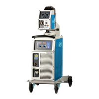
What to do if the shielding gas supply does not stop on my Daihen OTC CPTX-I 400 2W Inverter?
- SStephen WilliamsAug 1, 2025
If the shielding gas supply on your Daihen Inverter doesn't stop, it could be due to the gas check lamp being lit. Press the GAS CHECK key to stop the gas check. Alternatively, there might be an issue with the gas solenoid valve (SOL). In this case, check the operation of the gas solenoid valve (SOL) on the wire feeder.