-22-
3.5 Handling Instructions for RT series Torch
(1) Be sure to install an orifice. Installation of the orifice is essential, which prevents the short
circuit likely to happen between the nozzle and torch body, and also avoids turbulence of the
shield gas.
(2) Remove the spatter adhered to the nozzle and contact tip before it gets deposited.
(3) Be sure to use the DAIHEN genuine tip. Use of a worn-out tip with an enlarged diameter
causes conduction defect and wire deflection, which results in unstable Arc and aiming
deviation. Therefore, replace the tip accordingly before it gets used up.
(4) Gas flow shall be 15 l/min or more...
(5) Clean up the inside of liner (included in the coaxial power cable) and of outlet guide with
compressed air or others once in 10 days. Otherwise, deposit of sludge and dust will cause
defective wire feeding, which leads to poor welding performance.
(6) When the wire is stuck at the tip end, the wire will buckle in the liner or be cut in the feed roll.
If keeping wire feed performance under such a condition, feeding failure or Arc shortage may
occur. To prevent this, remove the wire between the feed roll and tip end first, and then insert
a new wire.
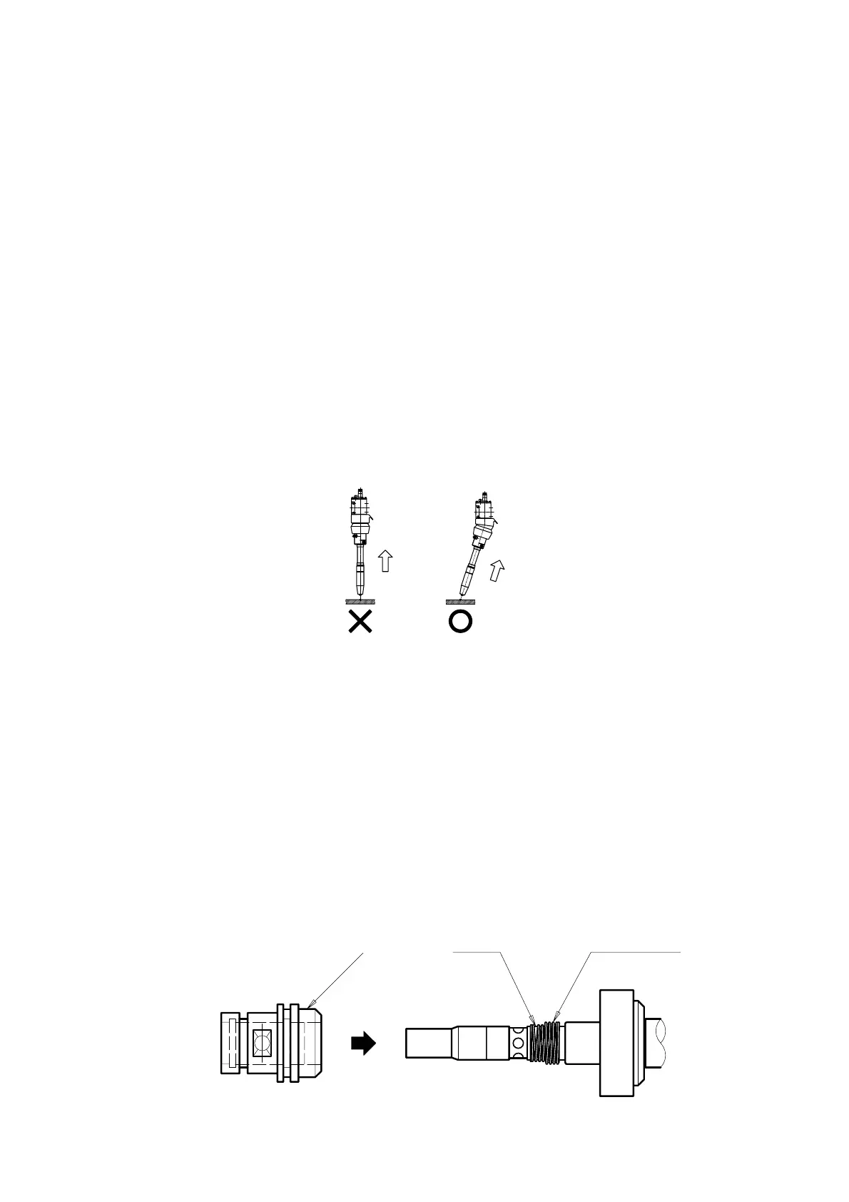
(7) For the teaching program that lets the torch evacuated from the workpiece after welding
performance, teach it to pull up the torch obliquely upward so that the shock sensor can work
even if the wire sticks on the workpiece.
Fig.3.18 Evacuating direction
(8) The shock sensor is the mechanism to protect the torch and manipulator in the case of collision
between the torch and workpiece, but does not guarantee the accuracy of the torch tip teaching
point (torch aiming point) afterward. After the shock sensor has worked, check the aiming
point of torch again with the torch gauge.
(9) When the screws (M5×20) fixing the torch are loose, the torch tip postion will be off. Tighten the
screws using the proper torque value. (See the pages 8, 9 and 13.)
(10) When replacing the O-ring of liquid-cooled torch, take enough care not to hurt the O-ring inside
the insulating bush by the screw part of tip body. (Refer to Fig.3.19)
(When mount the insulating bush, use the applicator. The applicator is attached component of
liquid-cooled torch.)
Blemish made in the O-ring will cause water leaks.
Fig.3.19 Replacement of O-ring
Insulating bush
Screw part
Applicator



 To Next Page