7 | Piping installation
Installer reference guide
42
2MXM40+50A
R32 Split series
4P600463-4E – 2021.12
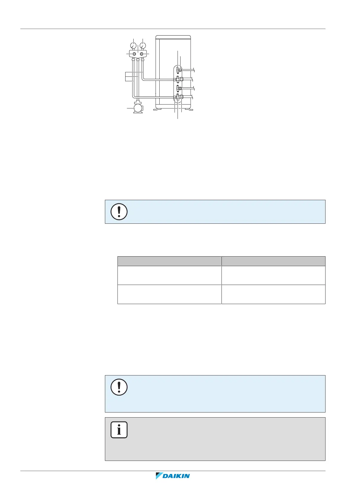
a Low pressure gauge
b Gauge manifold
c High pressure gauge
d Low-pressure valve (Lo)
e High-pressure valve (Hi)
f Charging hoses
g Vacuum pump
h Valve caps
i Service port
j Gas stop valve
k Liquid stop valve
NOTICE
Connect the vacuum pump to both the service ports of the gas stop valves.
1 Vacuum the system until the pressure on the manifold indicates −0.1 MPa
(−1bar).
2 Leave as is for 4-5minutes and check the pressure:
If the pressure… Then…
Does not change There is no moisture in the system.
This procedure is finished.
Increases There is moisture in the system. Go
to the next step.
3 Vacuum the system for at least 2hours to a manifold pressure of −0.1MPa
(−1bar).
4 After turning the pump OFF, check the pressure for at least 1hour.
5 If you do NOT reach the target vacuum or CANNOT maintain the vacuum for
1hour, do the following:
▪ Check for leaks again.
▪ Perform vacuum drying again.
NOTICE
Make sure to open the stop valves after installing the refrigerant piping and
performing vacuum drying. Running the system with the stop valves closed may
break the compressor.
INFORMATION
After opening the stop valve, it is possible that the pressure in the refrigerant piping
does NOT increase. This might be caused by e.g. the closed state of the expansion
valve in the outdoor unit circuit, but does NOT present any problem for correct
operation of the unit.