11 Maintenance and service
Installation manual
20
2MXM40+50A9
R32 Split series
3P600450-8T – 2022.09
11 Maintenance and service
NOTICE
General maintenance/inspection checklist. Next to the
maintenance instructions in this chapter, a general
maintenance/inspection checklist is also available on the
Daikin Business Portal (authentication required).
The general maintenance/inspection checklist is
complementary to the instructions in this chapter and can
be used as a guideline and reporting template during
maintenance.
NOTICE
Maintenance MUST be done by an authorised installer or
service agent.
We recommend performing maintenance at least once a
year. However, applicable legislation might require shorter
maintenance intervals.
NOTICE
Applicable legislation on fluorinated greenhouse gases
requires that the refrigerant charge of the unit is indicated
both in weight and CO
2
equivalent.
Formula to calculate the quantity in CO
2
equivalent
tonnes: GWP value of the refrigerant × total refrigerant
charge [in kg] / 1000
12 Disposal
NOTICE
Do NOT try to dismantle the system yourself: dismantling
of the system, treatment of the refrigerant, oil and other
parts MUST comply with applicable legislation. Units
MUST be treated at a specialised treatment facility for
reuse, recycling and recovery.
INFORMATION
To protect the environment, make sure to perform an
automatic pump down operation when relocating or
dismantling the unit. For the pump down procedure, refer
to the service manual or the installer reference guide.
13 Technical data
▪ A subset of the latest technical data is available on the regional
Daikin website (publicly accessible).
▪ The full set of latest technical data is available on the Daikin
Business Portal (authentication required).
13.1 Wiring diagram
The wiring diagram is delivered with the unit, located inside of
the outdoor unit (bottom side of the top plate).
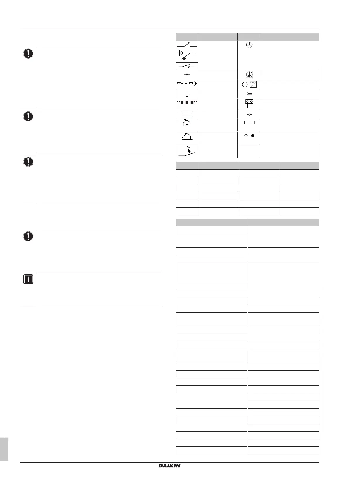
13.1.1 Unified wiring diagram legend
For applied parts and numbering, refer to the wiring diagram on the
unit. Part numbering is by Arabic numbers in ascending order for
each part and is represented in the overview below by "*" in the part
code.
Symbol Meaning Symbol Meaning
Circuit breaker Protective earth
Connection Protective earth (screw)
Connector
,
Rectifier
Earth Relay connector
Field wiring Short-circuit connector
Fuse Terminal
Indoor unit Terminal strip
Outdoor unit Wire clamp
Residual current
device
Symbol Colour Symbol Colour
BLK Black ORG Orange
BLU Blue PNK Pink
BRN Brown PRP, PPL Purple
GRN Green RED Red
GRY Grey WHT White
SKY BLU Sky blue YLW Yellow
Symbol Meaning
A*P Printed circuit board
BS* Pushbutton ON/OFF, operation
switch
BZ, H*O Buzzer
C* Capacitor
AC*, CN*, E*, HA*, HE*, HL*,
HN*, HR*, MR*_A, MR*_B, S*, U,
V, W, X*A, K*R_*, NE
Connection, connector
D*, V*D Diode
DB* Diode bridge
DS* DIP switch
E*H Heater
FU*, F*U, (for characteristics,
refer to PCB inside your unit)
Fuse
FG* Connector (frame ground)
H* Harness
H*P, LED*, V*L Pilot lamp, light emitting diode
HAP Light emitting diode (service
monitor green)
HIGH VOLTAGE High voltage
IES Intelligent eye sensor
IPM* Intelligent power module
K*R, KCR, KFR, KHuR, K*M Magnetic relay
L Live
L* Coil
L*R Reactor
M* Stepper motor
M*C Compressor motor
M*F Fan motor
M*P Drain pump motor
M*S Swing motor