13 Technical data
Installation manual
21
2MXM40+50A9
R32 Split series
3P600450-8T – 2022.09
Symbol Meaning
MR*, MRCW*, MRM*, MRN* Magnetic relay
N Neutral
n=*, N=* Number of passes through ferrite
core
PAM Pulse-amplitude modulation
PCB* Printed circuit board
PM* Power module
PS Switching power supply
PTC* PTC thermistor
Q* Insulated gate bipolar transistor
(IGBT)
Q*C Circuit breaker
Q*DI, KLM Earth leak circuit breaker
Q*L Overload protector
Q*M Thermo switch
Q*R Residual current device
R* Resistor
R*T Thermistor
RC Receiver
S*C Limit switch
S*L Float switch
S*NG Refrigerant leak detector
S*NPH Pressure sensor (high)
S*NPL Pressure sensor (low)
S*PH, HPS* Pressure switch (high)
S*PL Pressure switch (low)
Symbol Meaning
S*T Thermostat
S*RH Humidity sensor
S*W, SW* Operation switch
SA*, F1S Surge arrester
SR*, WLU Signal receiver
SS* Selector switch
SHEET METAL Terminal strip fixed plate
T*R Transformer
TC, TRC Transmitter
V*, R*V Varistor
V*R Diode bridge, Insulated-gate
bipolar transistor (IGBT) power
module
WRC Wireless remote controller
X* Terminal
X*M Terminal strip (block)
Y*E Electronic expansion valve coil
Y*R, Y*S Reversing solenoid valve coil
Z*C Ferrite core
ZF, Z*F Noise filter
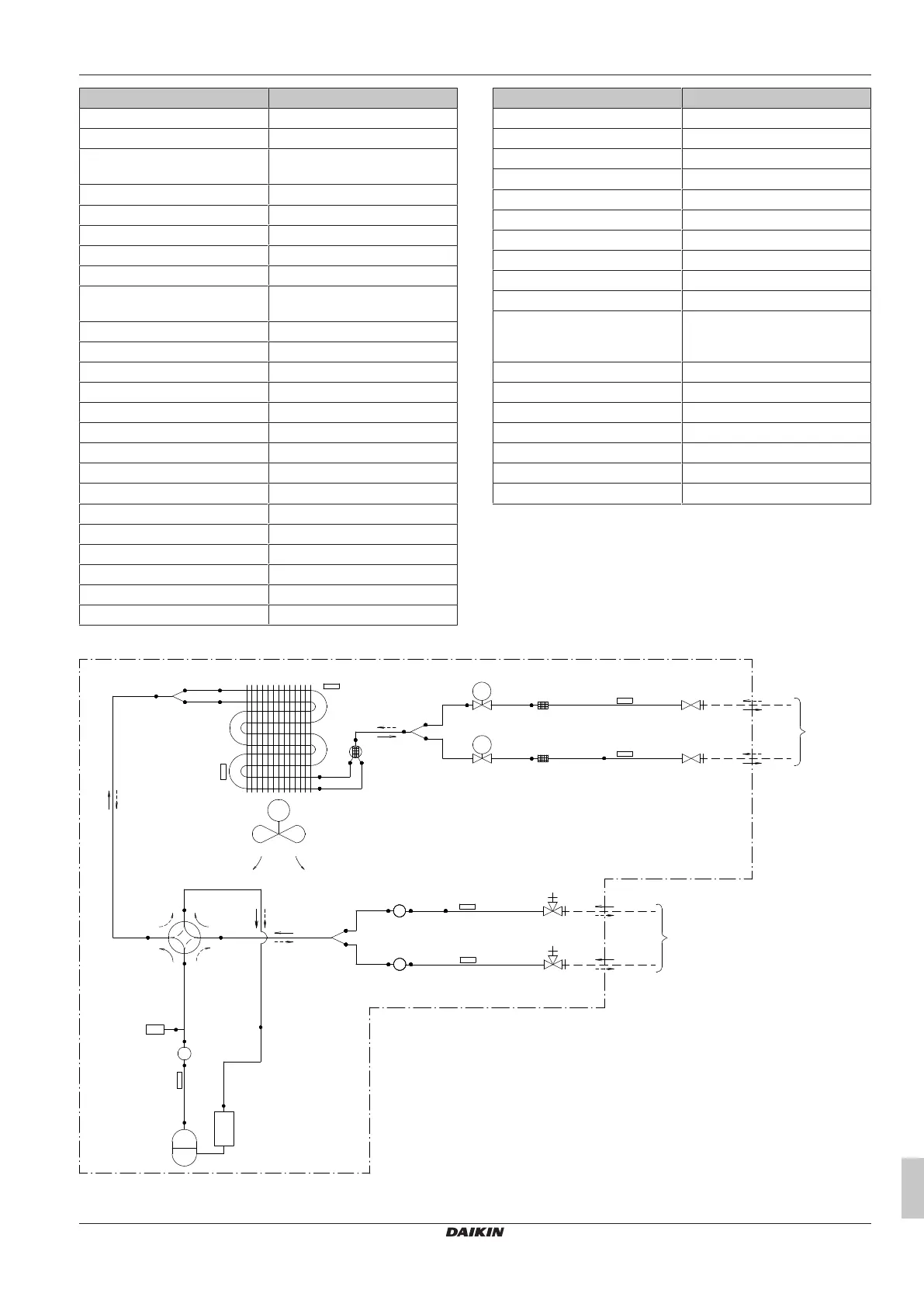
13.2 Piping diagram: Outdoor unit
Component PED category classification:
▪ High pressure switches: category IV
▪ Compressor: category II
▪ Other components: refer to PED article 4, paragraph 3
7.9CuT
7.9CuT
M
4.8CuT
4.8CuT
9.5CuT
7.9CuT
9.5CuT
9.5CuT
9.5CuT
9.5CuT
9.5CuT
6.4CuT
6.4CuT
EV
A
EV
B
9.5CuT
6.4CuT
6.4CuT
6.4CuT
9.5CuT
9.5CuT
HPS1
9.5CuT
(9.5CuT)
(12.7CuT)
(6.4CuT)
(6.4CuT)
a
b
c
d
e
f
g
g
h
i
j
A
B
A
B
k
l
l
m
n
o
o
p
q
r
s
t
n
m
i
h
g
c
c
2MXM50
A Room A k Field piping (liquid)
B Room B l Liquid stop valve
 Loading...