5 Piping installation
Installation manual
16
2(A)MXM40+50 + 2(A)MXF40+50
R32 Split series
3P600450-3G – 2021.03
Port Class Reducer
B 25, 35 —
2MXF40
A 20, 25, 35 —
B 20, 25, 35 —
2MXM50, 2AMXM50
A 15, 20, 25, 35, 42
(a)
—
B 15, 20, 25, 35 1+2
42, 50 —
2AMXF50
A 25, 35 —
B 25, 35 1+2
2MXF50
A 20, 25, 35 —
B 20, 25, 35 1+2
(a)
Use optional accessory.
Reducer type Connection
1 Ø12.7mm → Ø9.5mm
2 Ø12.7mm → Ø9.5mm
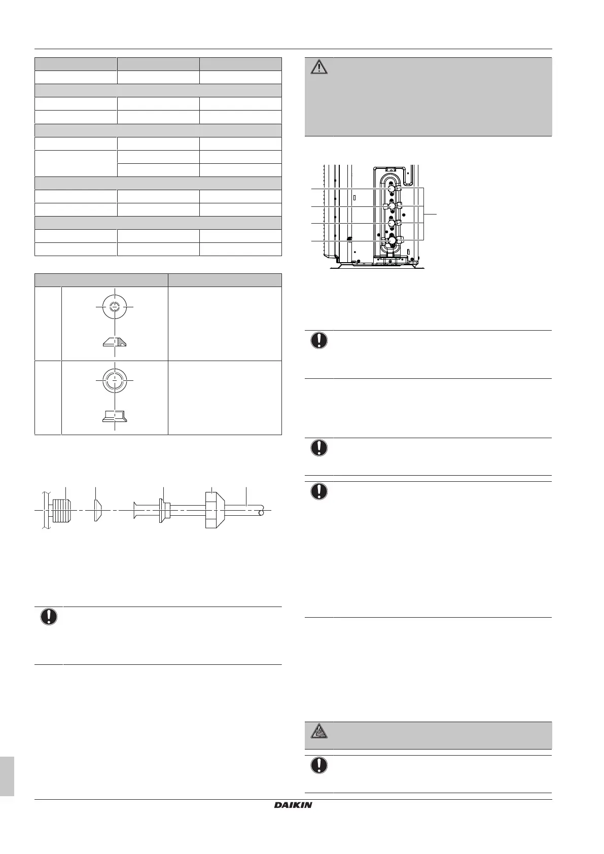
Connection example:
▪ Connecting a Ø9.5mm pipe to a Ø12.7mm gas pipe connection
port
a Outdoor unit connection port
b Reducer type 1
c Reducer type 2
d Flare nut for Ø12.7mm
e Inter-unit piping
Coat the threaded connection port of the outdoor unit where the flare
nut comes in with refrigeration oil.
NOTICE
Use an appropriate wrench to avoid damaging the
connection thread by overtightening the flare nut. Be
careful NOT to overtighten the nut, or the smaller pipe may
be damaged (about 2/3-1× the normal torque).
5.2.2 To connect the refrigerant piping to the
outdoor unit
▪ Piping length. Keep field piping as short as possible.
▪ Piping protection. Protect the field piping against physical
damage.
WARNING
Connect the refrigerant piping securely before running the
compressor. If the refrigerant piping is NOT connected and
the stop valve is open when the compressor is run, air will
be sucked in. This will cause abnormal pressure in the
refrigeration cycle, which may result in equipment damage
and even injury.
1 Connect the liquid refrigerant connection from the indoor unit to
the liquid stop valve of the outdoor unit.
a Liquid stop valve
b Gas stop valve
c Service port
2 Connect the gas refrigerant connection from the indoor unit to
the gas stop valve of the outdoor unit.
NOTICE
It is recommended that the refrigerant piping between
indoor and outdoor unit is installed in a ducting or the
refrigerant piping is wrapped with finishing tape.
5.3 Checking the refrigerant piping
5.3.1 To check for leaks
NOTICE
Do NOT exceed the unit's maximum working pressure (see
"PS High" on the unit name plate).
NOTICE
ALWAYS use a recommended bubble test solution from
your wholesaler.
NEVER use soap water:
▪ Soap water may cause cracking of components, such
as flare nuts or stop valve caps.
▪ Soap water may contain salt, which absorbs moisture
that will freeze when the piping gets cold.
▪ Soap water contains ammonia which may lead to
corrosion of flared joints (between the brass flare nut
and the copper flare).
1 Charge the system with nitrogen gas up to a gauge pressure of
at least 200 kPa (2 bar). It is recommended to pressurize to
3000kPa (30bar) in order to detect small leaks.
2 Check for leaks by applying the bubble test solution to all
connections.
3 Discharge all nitrogen gas.
5.3.2 To perform vacuum drying
DANGER: RISK OF EXPLOSION
Do NOT start the unit if it is vacuumed.
NOTICE
Connect the vacuum pump to both the service ports of the
gas stop valves.
 Loading...