7 Installation
Installer reference guide
40
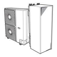
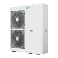
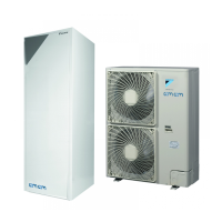
ERHQ+ERLQ011~016 + EHVH/X11+16S18+26CB
Daikin Altherma – Low temperature split
4P384975-1C – 2018.02
Wire type Installation method
Single-core wire
a Curled single-core wire
b Screw
c Flat washer
Stranded conductor
wire with round
crimp-style terminal
a Terminal
b Screw
c Flat washer
O Allowed
X NOT allowed
Tightening torques
Item Tightening torque (N•m)
M4 (X1M) 1.2~1.8
M5 (X1M) 2.0~3.0
M5 (earth) 3.0~4.0
7.9.5 Specifications of standard wiring
components
Component V3 W1
ERHQ ERLQ ERHQ ERLQ
Power supply
cable
MCA
(a)
31.9A 34.2A 13.5A 16.3A
Voltage 230V 400V
Phase 1~ 3N~
Frequency 50Hz
Wire sizes Must comply with applicable
legislation
Interconnection cable Minimum cable section of 2.5mm²
and applicable for 230V
Recommended field fuse 32A 40A 20A
Earth leakage circuit breaker Must comply with applicable
legislation
(a) MCA=Minimum circuit ampacity. Stated values are
maximum values (see electrical data of combination with
indoor units for exact values).
7.9.6 To connect the electrical wiring on the
outdoor unit
NOTICE
▪ Follow the wiring diagram (delivered with the unit,
located at the inside of the service cover).
▪ Make sure the electrical wiring does NOT obstruct
proper reattachment of the service cover.
1 Remove the service cover. See "7.2.2 To open the outdoor
unit"on page28.
2 Strip insulation (20mm) from the wires.
a Strip wire end to this point
b Excessive strip length may cause electrical shock or
leakage.
3 Connect the interconnection cable and power supply as follows:
c
b
a
d
V3
1~ 50 Hz
230 V
W1
3N~ 50 Hz
400 V
L1 L3L2
L1 L3L2
a Interconnection cable
b Power supply cable
c Earth leakage circuit breaker
d Fuse
a Switch box
b Stop valve attachment plate
c Earth
d Cable tie
e Interconnection cable
f Power supply cable
Only if bottom plate heater is installed (option for ERHQ):
g Bottom plate heater cable
h Power supply cable of the bottom plate heater (from the
indoor unit)
INFORMATION
ERLQ units control the bottom plate heater internally (field
wiring NOT required).
 Loading...