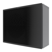
Do you have a question about the Daikin ATX35JV1B and is the answer not in the manual?
Details the various functions supported by the HVAC system models.
Provides detailed specifications for different types of indoor units.
Provides detailed specifications for outdoor unit models.
Wiring diagrams for various indoor unit models and their PCBs.
Wiring diagrams for wired remote controllers like BRC1D528 and BRC1E51A7.
Wiring diagrams for wireless remote controllers like BRC7E530W.
Wiring diagrams for outdoor units, detailing PCB connections.
Explains various functions and controls of the RA indoor unit.
Details functions and controls specific to SA indoor units.
Describes the purpose and function of various thermistors in the system.
Outlines system control specifications, including modes and frequency.
Details remote controller operations for RA indoor units, listing model compatibility.
Details remote controller operations for SA indoor units, listing model compatibility.
Guides on troubleshooting indoor and outdoor unit errors indicated by LEDs.
Lists common problem symptoms and their corresponding troubleshooting measures.
Explains how to use service check functions on remote controllers for diagnosis.
Lists error codes displayed on remote controllers and their reference pages.
Provides detailed troubleshooting steps for RA indoor unit abnormalities.
Provides detailed troubleshooting steps for SA indoor unit abnormalities.
Guides on troubleshooting various error codes and symptoms for outdoor units.
Details specific checks for components like thermistors, motors, and PCBs.
Procedure for safely removing refrigerant before relocation or disposal.
Instructions for performing a forced cooling operation test.
Steps for conducting trial operation to verify system functionality.
Covers settings adjustment for indoor units based on installation type and model.
Guidance on applying silicon grease during PCB replacement for heat dissipation.
Visual representation of refrigerant piping for indoor units by type.
Electrical wiring diagrams for indoor and outdoor units, detailing connections.
References to specific booklets for component removal procedures.


