Do you have a question about the Daikin ATX25JV1B and is the answer not in the manual?
Lists all functions available for various indoor unit models, categorized by type.
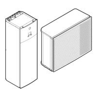
Detailed specifications for various wall-mounted, floor-standing, and cassette indoor units.
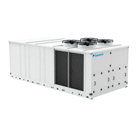
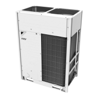
Detailed specifications for various outdoor unit models, including dimensions and performance data.
Wiring diagrams for indoor unit PCBs, detailing connector locations and functions.
Wiring diagrams for wired remote controllers (BRC1D528, BRC1E51A7).
Wiring diagrams for wireless remote controller (BRC7E530W).
Wiring diagrams for outdoor unit PCBs, detailing connector locations and functions.
Provides an overview of the manual and safety information.
Details critical safety warnings and precautions for installation and repair.
Specific safety warnings for personnel performing repair or installation work.
Specific safety warnings and precautions for end-users to ensure safe operation.
Explains the meaning of various icons used throughout the manual for clarity.
Explains various operational functions of RA indoor units like temperature and airflow control.
Explains various operational functions of SA indoor units, including drain pump and thermostat control.
Details the role and types of thermistors used in system control and operation.
Outlines system control logic, including mode hierarchy, frequency control, and protection functions.
Details the functions and operation of RA indoor units via the remote controller.
Details the functions and operation of SA indoor units via the remote controller.
Guides on troubleshooting indoor and outdoor unit errors indicated by LED status.
Provides a table of common symptoms and their corresponding solutions.
Describes diagnostic modes for remote controllers (ARC466, ARC452 series).
Lists error codes displayed on remote controllers for RA and SA indoor units.
Detailed troubleshooting guide for various abnormalities in RA indoor units.
Detailed troubleshooting guide for various abnormalities in SA indoor units.
Comprehensive guide to troubleshooting common issues with outdoor units.
Lists various checks and tests for diagnosing system components and performance.
Procedure for safely removing refrigerant before relocating or disposing of the unit.
Describes how to activate and use the forced cooling operation mode.
Steps for performing trial operation to verify system functionality after installation.
Instructions for configuring various settings of indoor and outdoor units via remote controller.
Guidelines for applying silicon grease when replacing PCBs for heat dissipation.
Visual representations of refrigerant piping for various indoor unit types.
Electrical wiring diagrams for indoor and outdoor units, showing component connections.
References to separate booklets for component removal procedures.
| Model | ATX25JV1B |
|---|---|
| Category | Heat Pump |
| Cooling Capacity | 2.5 kW |
| Heating Capacity | 3.2 kW |
| Refrigerant | R32 |
| Power Supply | 220-240V, 50Hz |
| Coefficient of Performance (COP) | 4.00 |
| Noise Level (Outdoor Unit) | 48 dBA |