English 15
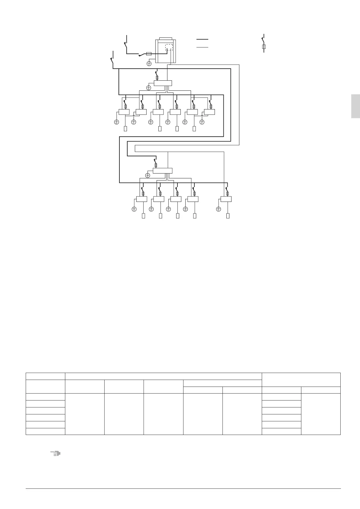
8-2 EXAMPLE FOR THE WHOLE SYSTEM
Power supply
Indoor unit
Indoor unit
Remote controller
Remote controller
Remote controller
Power supply
Outdoor unit
Main
switch
Main
switch
Power supply wiring
Transmission wiring
Switch
Fuse
BS4Q unit
BS4Q unit
Cooling-dedicated
indoor unit
8-3 POWER CIRCUIT, SAFETY DEVICE AND CABLE REQUIREMENTS
•
A power circuit (Refer to Table 6) must be provided for connection of the unit. This circuit must be protected with the
required safety devices, i.e. a main switch, a slow blow fuse on each phase and an earth leakage circuit breaker.
• When using residual current operated circuit breakers, be sure to use a high-speed type (0.1 second or
less) 30mA rated residual operating current.
• Use copper conductors only.
• Use insulated wire for the power cord.
• Select the power supply cable type and size in accordance with relevant local and national regulations.
• Specications for local wiring are in compliance with IEC60245.
• Use wire type H05VV-U3G for power supply wiring. And the size must comply with local codes.
• Use vinyl cord with sheath or cable (2 wire) of 0.75-1.25mm
2
for transmission wiring.
• The transmission wire lengths are as follows:
Between the BS unit and indoor units: Max. 1,000 m
Between the BS unit and outdoor unit: Max. 1,000 m
Between BS units: Max. 1,000 m
Total wiring length: 2,000 m or less
Table 6
Units
Power supply
Model Type Hz Voltage
Voltage range
Min. Max. MCA MFA
BS4Q14AV1
V1 50 220-240 198 264
0.4
15
BS6Q14AV1 0.6
BS8Q14AV1 0.8
BS10Q14AV1 1.0
BS12Q14AV1 1.2
BS16Q14AV1 1.6
MCA: Min. Circuit Amps (A); MFA: Max. Fuse Amps (A)
NOTES
• The above Table 6 of Electrical Characteristics refers to one BS unit.
01_EN_3P194121-8U.indd 15 2/21/2014 3:31:12 PM