16 English
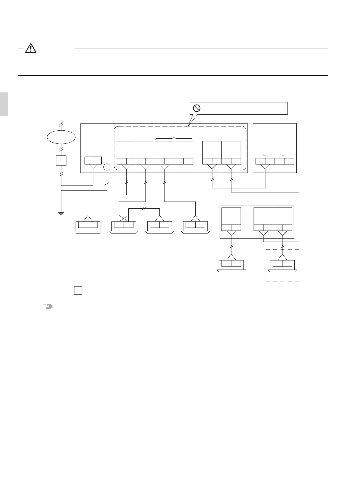
8-4 Wiring example
Here is shown a wiring example for transmission wiring.
WARNING
Install an earth leakage circuit breaker.
Failure to install an earth leakage circuit breaker may result in electric shock or re.
• Connect terminals F1 and F2 (IN/OUT) on the control Printed Circuit Board in the outdoor unit’s control
box to terminals F1 and F2 (outdoor unit) on the rst BS unit.
F1 F2 F1 F2 F1 F2 F1 F2 F1 F2 F1 F2 F1 F2 F1 F2
F1 F2F1 F2
F1 F2F1 F2F1 F2F1 F2
F1 F2 F1 F2 F1 F2
LB
E
D
220-240V
N
Indoor
unit
A
Indoor
unit
B
Indoor
unit
C
Indoor
unit
D
Outdoor
unit
BS unit
BS unit
Outdoor unit
To BS unit
Cooling-dedicated
unit (Note 1)
Indoor unit
A
Indoor unit
B-1
Indoor unit
B-2 (Note 3)
Indoor unit
C (Note 2)
Indoor unit Indoor unit
OUTOUT OUTIN
Never connect to power supply wiring.
When joining branch pipes
Indoor
unit
Outdoor
unit
BS unit
B
: earth leakage circuit breaker
Power supply
NOTES
1.
Connect the cooling-dedicated unit to the nal BS unit’s F1 and F2 terminals (outdoor side).
2. This wiring example applies when joining the C and D branches and connecting them to indoor units.
The terminal block to which the transmission wiring is connected can be connected to either indoor unit
C or indoor unit D.
However, the DIP switches must be set appropriately.
For more information about how to set DIP switches, refer to “9. INITIAL SETTING”.
3. The maximum connection number of indoor units per branch is 5 sets.
01_EN_3P194121-8U.indd 16 2/21/2014 3:31:12 PM