Check Si12-411A
206 Service Diagnosis
6. Check
6.1 How to Check
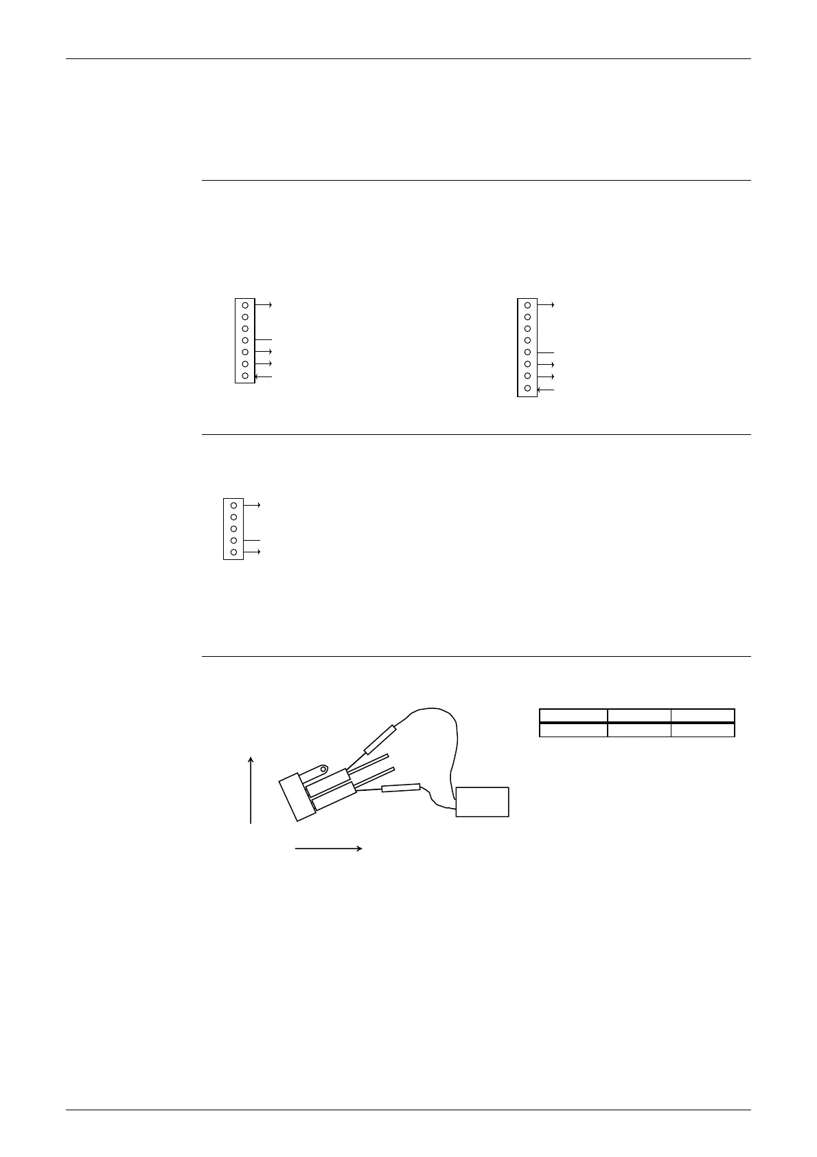
6.1.1 Fan Motor Connector Output Check
Check No.01 1. Check connector connection.
2. Check motor power supply voltage output (pins 4-7 and 4-8).
3. Check motor control voltage (pins 4-3).
4. Check rotation command voltage output (pins 4-2).
5. Check rotation pulse input (pins 4-1).
Check No.02 1. Check connector connection.
2. Check motor control voltage output (pins 2-1).
6.1.2 Limit Switch Continuity Check
Check No.3 Remove the front grille. The limit switch is located at the left side of the drain pan assembly.
Check the continuity of the switch connection.
∗ The shutter can be opened and closed with hand. Keep the shutter open and closed all the
way for each continuity check steps.
7
6
5
4
3
2
1
Motor power supply voltage
Unused
Unused
P.0V (reference potential)
Motor control voltage (15 VDC)
Rotation command voltage (1~ 5 VDC)
Rotation pulse input
Upper fan connector
8
7
6
5
4
3
2
1
Motor power supply voltage
Unused
Unused
Unused
P.0V (reference potential)
Motor control voltage (15 VDC)
Rotation command voltage (1 to 5 VDC)
Rotation pulse input
Lower fan connector
(R1224)
5
4
3
2
1
Motor power supply voltage
Unused
Unused
P.0V (reference potential)
Motor control power supply
S202
(R1073)
Tester
Limit switch
Forward
Upward
Shutter status
Continuity
Closed
No continuity
Open
Continuity
(Q0363)