EasyManua.ls Logo

Daikin ComfortNet DX7TC User Manual

Daikin ComfortNet DX7TC
122 pages
To Next Page IconTo Next Page
Page #1 background imageLoading...
Page #1 background image

This manual is to be used by qualied, professionally trained HVAC technicians only. Daikin does
not assume any responsibility for property damage or personal injury due to improper service
procedures or services performed by an unqualied person.
RSD6200007r24
May 2023
ONLY PERSONNEL THAT HAVE BEEN TRAINED TO INSTALL, ADJUST,
SERVICE, MAINTENANCE OR REPAIR (HEREINAFTER, “SERVICE”)
THE EQUIPMENT SPECIFIED IN THIS MANUAL SHOULD SERVICE THE
EQUIPMENT.
THIS EQUIPMENT IS NOT INTENDED FOR USE BY PERSONS (INCLUDING
CHILDREN) WITH REDUCED PHYSICAL, SENSORY OR MENTAL CAPABILITIES,
OR LACK OF EXPERIENCE AND KNOWLEDGE, UNLESS THEY HAVE BEEN
GIVEN SUPERVISION OR INSTRUCTION CONCERNING USE OF THE
APPLIANCE BY A PERSON RESPONSIBLE FOR THEIR SAFETY.
CHILDREN SHOULD BE SUPERVISED TO ENSURE THAT THEY DO NOT PLAY
WITH THE EQUIPMENT.
THE MANUFACTURER WILL NOT BE RESPONSIBLE FOR ANY INJURY OR
PROPERTY DAMAGE ARISING FROM IMPROPER SUPERVISION, SERVICE
OR SERVICE PROCEDURES. IF YOU SERVICE THIS UNIT, YOU ASSUME
RESPONSIBILITY FOR ANY INJURY OR PROPERTY DAMAGE WHICH MAY
RESULT. IN ADDITION, IN JURISDICTIONS THAT REQUIRE ONE OR MORE
LICENSES TO SERVICE THE EQUIPMENT SPECIFIED IN THIS
MANUAL, ONLY LICENSED PERSONNEL SHOULD SERVICE THE EQUIPMENT.
IMPROPER SUPERVISION, INSTALLATION, ADJUSTMENT, SERVICING,
MAINTENANCE OR REPAIR OF THE EQUIPMENT SPECIFIED IN THIS
MANUAL, OR ATTEMPTING TO INSTALL, ADJUST, SERVICE OR REPAIR THE
EQUIPMENT SPECIFIED IN THIS MANUAL WITHOUT PROPER SUPERVISION
OR TRAINING MAY RESULT IN PRODUCT DAMAGE, PROPERTY DAMAGE,
PERSONAL INJURY OR DEATH.
WARNING
WARNING
DO NOT BYPASS SAFETY DEVICES.
TABLE OF CONTENTS
Important Informaon ................................................................2
Product Idencaon ..................................................................4
Accessories ................................................................................21
Product Design ..........................................................................28
System Operaon ......................................................................31
Troubleshoong Chart ...............................................................35
Servicing Table of Contents .......................................................36
Servicing ....................................................................................37
Wiring Diagrams ......................................................................117
Copyright © 2021-2023
ComfortNet™

DZ7TC, DZ16TC & DZ18TC Split System Heat Pumps



Table of Contents

Question and Answer IconNeed help?

Do you have a question about the Daikin ComfortNet DX7TC and is the answer not in the manual?

Daikin ComfortNet DX7TC Specifications

General IconGeneral
Energy MonitoringYes
RefrigerantR-410A
CompatibilityDaikin ComfortNet communicating HVAC systems
Cooling Capacity18, 000 - 60, 000 BTU/h
Heating Capacity18, 000 - 60, 000 BTU/h

Summary

Important Information

Important Notices

Notices regarding safety symbols, words, and labels.

Safe Refrigerant Handling

Guidelines for safe refrigerant handling.

Product Identification

DX16TC / DX18TC Condensing Units

Details for Daikin 16 SEER and 18 SEER AC units.

DZ16TC / DZ18TC Heat Pumps

Details for Daikin 16 SEER and 18 SEER Heat Pump units.

CAUF Indoor Coils

Details for CAUF series indoor coils.

CAPT Indoor Coils

Details for CAPT series indoor coils.

Accessories

DX16TC / DX18TC Accessories

List of accessories for DX16TC/DX18TC condensing units.

DZ7TC Accessories

List of accessories for DZ7TC heat pumps.

Electric Heat Kits for MBVC

Electric heat kit applications for MBVC blower units.

Product Design

Condensing Unit

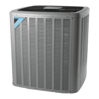
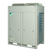
Description of the condensing unit's components and operation.

Capacity Control - ComfortNet™ Models

Explanation of capacity control for ComfortNet models.

Communicating Unitary Control (UC) PCB

Description of the UC PCB and its functions.

System Operation

Cooling Cycle

Explanation of the system's cooling cycle and refrigerant.

Heating Cycle

Explanation of the system's heating cycle.

Defrost Cycle - ComfortNet™ Models

Explanation of the defrost cycle for ComfortNet models.

Troubleshooting Charts

Cooling/HP Analysis Chart

Chart for diagnosing cooling/heat pump issues.

Servicing

S-1 Checking Voltage

Procedure for checking unit voltage.

S-9 Checking High and Low Voltage to ECM Motor

Checking high/low voltage to ECM motor.

S-15 Checking Capacitor

Procedure for checking the run capacitor.

S-17 Checking Compressor

Procedures for checking the compressor.

S-103 Charging

Procedures for charging the system with refrigerant.

S-115 Compressor Burnout

Troubleshooting compressor burnout.

Troubleshooting Error Codes

AC - No Cool

Troubleshooting flowchart for AC no-cool issues.

Heat Pump - No Cool

Troubleshooting flowchart for heat pump no-cool issues.

Error Code - 01, L1

Troubleshooting for error code 01, L1.

Error Code - 02, L2

Troubleshooting for error code 02, L2.

Error Code - B0 & B1

Troubleshooting for error codes B0 and B1.

Error Code - B2-B6, B9

Troubleshooting for error codes B2-B6, B9.

Error Code - D0, D1, D4

Troubleshooting for error codes D0, D1, D4.

Error Code - EC

Troubleshooting for error code EC (Heater mismatch).

Wiring Diagrams

Two-Stage Integrated Control Module

Wiring diagram for the integrated control module.

DV**PTC/MBVC

Wiring diagram for DV**PTC/MBVC units.

3-Phase Heat Kit

Wiring diagram for a 3-phase heat kit.

DX16TC

Wiring diagram for the DX16TC model.

DX18TC, DX7TC

Wiring diagram for DX18TC and DX7TC models.

Related product manuals