Do you have a question about the Daikin CTXS09GVJU and is the answer not in the manual?
Read and follow safety considerations before installing and operating the equipment.
Details the connector wiring diagrams for internal circuit boards.
Provides wiring diagram details for indoor unit circuit boards.
Details wiring diagrams for outdoor unit circuit boards.
Lists and describes various malfunctions detected by the system.
Details the function for automatically detecting and correcting wiring errors.
Details essential safety precautions for users to prevent hazards and ensure proper use.
Offers guidance for diagnosing and resolving common operational issues.
Provides essential warnings and precautions before performing diagnostic procedures.
Lists common problems and their corresponding diagnostic measures and solutions.
Details error codes displayed on the remote controller and their descriptions.
Lists and describes all error codes displayed on the remote controller.
Provides detailed troubleshooting steps for various system faults and abnormalities.
Troubleshooting steps for issues related to indoor units.
Troubleshooting steps for issues related to outdoor units.
Troubleshooting steps for indoor unit PCB abnormalities.
Troubleshooting for freeze-up protection or high pressure control issues.
Troubleshooting steps for fan motor and related abnormalities.
Troubleshooting steps for indoor unit thermistor abnormalities.
Troubleshooting steps for signal transmission errors between units.
Troubleshooting steps for unspecified voltage between units.
Troubleshooting steps for freeze-up protection control issues.
Troubleshooting steps for outdoor unit PCB abnormalities.
Troubleshooting steps for OL activation or compressor overload.
Troubleshooting steps for compressor lock issues.
Troubleshooting steps for DC fan lock issues.
Troubleshooting steps for input over current detection.
Troubleshooting steps for four-way valve abnormalities.
Troubleshooting steps for discharge pipe temperature control issues.
Troubleshooting steps for high pressure control in cooling mode.
Troubleshooting steps for compressor sensor system abnormalities.
Troubleshooting steps for position sensor abnormalities.
Troubleshooting steps for CT or related abnormalities.
Troubleshooting steps for outdoor unit thermistor abnormalities.
Troubleshooting steps for electrical box temperature rise.
Troubleshooting steps for radiation fin temperature rise.
| Model | CTXS09GVJU |
|---|---|
| Category | Heat Pump |
| Heating Seasonal Performance Factor (HSPF) | 10.0 |
| Refrigerant | R-410A |
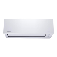
| Weight (Indoor Unit) | 8 kg |
| Power Supply | 220-240V, 50Hz |
| Cooling Capacity | 9000 BTU/h |
| Noise Level (Indoor) | 19 dB(A) |
| Dimensions (Indoor Unit) | 200 mm |
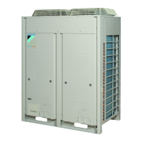
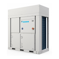
| Outdoor Unit Dimensions (HxWxD) | 550 x 780 x 285 mm |