Do you have a question about the Daikin DCG Series and is the answer not in the manual?
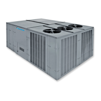
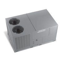
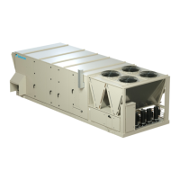
Manual covers Daikin gas electric, cooling, and heat pump package units.
Covers essential safety and usage guidelines for users and service technicians.
Provides critical safety instructions for handling refrigerants to prevent injury or death.
Explains how to interpret the model number for unit identification and parts.
Details various factory-installed options available for the units.
Specifies essential requirements for unit placement to ensure safety and proper operation.
Lists critical precautions for handling and installing the unit.
Defines necessary clearances around the unit for service, maintenance, and operation.
Provides essential information and warnings regarding unit electrical connections.
Highlights critical safety warnings related to high voltage components and wiring.
Details the requirements for connecting the main power supply to the unit.
Explains the wiring requirements for thermostats and control systems.
Critical safety instructions that must be read and understood before operating the unit.
Step-by-step guide on how to operate the unit for heating and cooling.
Describes the operational flow for cooling mode in gas or electric units.
Details the operational modes and cycles of the heat pump system.
Provides guidelines for proper gas supply piping installation and safety.
Specific instructions and warnings for installing propane gas systems.
Installation guidelines specific to roof-mounted units.
Crucial post-installation steps including initial setup and checks.
Guidance on adjusting airflow for optimal unit performance.
Describes the standard operating sequence for heating and cooling cycles.
Explains the defrost cycle operation for heat pump units.
Procedures for checking the integrity and function of the refrigeration system.
List of recommended periodic maintenance tasks for the unit.
Guidance on filter replacement frequency and importance.
Procedure for cleaning and checking the flame sensor.
Troubleshooting guide for cooling-related issues and their causes.
Troubleshooting guide for gas heating issues and their causes.
Procedure for checking supply and operating voltages.
Diagnosing and correcting voltage imbalance issues.
Diagnosing issues with the transformer and control circuit.
Diagnosing problems with the high-pressure safety control.
Procedures for testing run and start capacitors.
Procedures for testing compressor windings for continuity and ground.
Diagnosing issues with the reversing valve and its solenoid.
General troubleshooting guide for unit operational issues.
Procedures for safely testing the refrigeration system for leaks.
Steps for properly evacuating the refrigeration system.
Procedure for measuring and verifying superheat levels.
Procedure for measuring and verifying subcooling levels.
Diagnosing and correcting refrigerant overcharge issues.
Measuring and evaluating external static pressure in ductwork.
Testing the function of the primary limit control switch.
Testing the flame rollout safety switch for proper operation.
Steps for testing the gas valve for proper function.
Measuring and adjusting inlet and manifold gas pressures.
Procedures for testing the ignition control module.
Procedure for testing the flame sensor's signal output.
List of available accessory kits for Daikin units.
Wiring schematic for the economizer accessory.
Wiring diagram for the powered convenience outlet accessory.
Wiring diagram for the DPE90150 power exhaust accessory.
Wiring diagram for single-stage electric heat configurations.
Wiring diagram for two-stage electric heat configurations.
Wiring for heat pumps with two-stage electric heat.
Wiring diagram for low ambient kits on specific DCC/DCG models.
List of available part numbers for various heater kits.
Specifies minimum airflow requirements for electric heater kits.
Wiring diagram for EHK*-16 heater kits, pre-serial 1409.
Wiring diagram for EHK[3, 4, 7]-30 heater kits, pre-serial 1409.
Wiring diagram for EHK*-16 heater kits, serial 1409 and newer.
Wiring diagram for specific DCC models (090-150XXX*B***A*).
Wiring diagram for specific DCC models (090,102)XXX*V***A*.
Wiring diagram for specific DCG models (120,150)XXX*V***A*.
Wiring diagrams for DCH Commercial Heat Pump units.
Wiring diagram for specific DCH models (090-150XXX*B***A*).
Wiring diagram for specific DCG models (090-150XXX[4,7]B***A*).
Wiring diagram for specific DCG models (090,102)XXX3V***A*.
Wiring diagram for specific DCG models (090,102)XXX[4,7]V***A*.
Wiring diagram for specific DCG models (120,150)XXX3V***A*.
Wiring diagram for specific DCG models (120,150)XXX[4,7]V***A*.
| Refrigerant | R32 |
|---|---|
| Energy Efficiency Ratio (EER) | Varies depending on model. Refer to specific model's datasheet. |
| Coefficient of Performance (COP) | Varies depending on model. Refer to specific model's datasheet. |
| Noise Level (Outdoor Unit) | 45 dB - 58 dB |
| Power Supply | 220-240 V, 50 Hz |
| Indoor Unit Dimensions (HxWxD) | Varies depending on model. Refer to specific model's datasheet. |
| Outdoor Unit Dimensions (HxWxD) | Varies depending on model. Refer to specific model's datasheet. |
| Indoor Unit Weight | Varies depending on model. Refer to specific model's datasheet. |
| Outdoor Unit Weight | Varies depending on model. Refer to specific model's datasheet. |