Do you have a question about the Daikin DX16 and is the answer not in the manual?
General safety notices and warnings for consumers and service technicians regarding equipment.
Critical warnings concerning property damage, personal injury, or death from improper use.
Guidelines and warnings for the safe handling of refrigerants, including ventilation and protective gear.
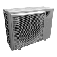
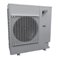
Product identification for Light Commercial Condensers and Heat Pumps, listing models.
Description of the cooling cycle, refrigerants, and indoor coil function.
Description of the heating cycle, reversing valve operation, and coil functions.
Explanation of the defrost cycle control and timing mechanisms.
Warning about high voltage hazards during servicing or installation.
Table correlating symptoms, possible causes, and test methods for troubleshooting.
Procedures for checking wiring, transformers, contactors, relays, and thermostats.
Procedures for checking capacitors, motor windings, and EEM blower replacement.
Procedures for testing compressor resistance, ground faults, unloaders, and rotation.
Procedures for checking reversing valves, defrost controls, thermostats, and heater components.
Guidance on leak testing, evacuation, charging, TXV, superheat, subcooling, and restrictions.
Procedures for diagnosing compressor burnout and cleaning the system.
Methods for measuring duct and coil static pressures for proper airflow diagnosis.
Wiring diagram for the AFE18-60A control board used in heat pumps with furnaces.
Typical wiring schematics for OT/EHR18-60 with one-stage and two-stage electric heat.
Typical wiring schematics for ASPT/ASUF models with electric heat.
| Brand | Daikin |
|---|---|
| Model | DX16 |
| Category | Air Conditioner |
| Language | English |