13
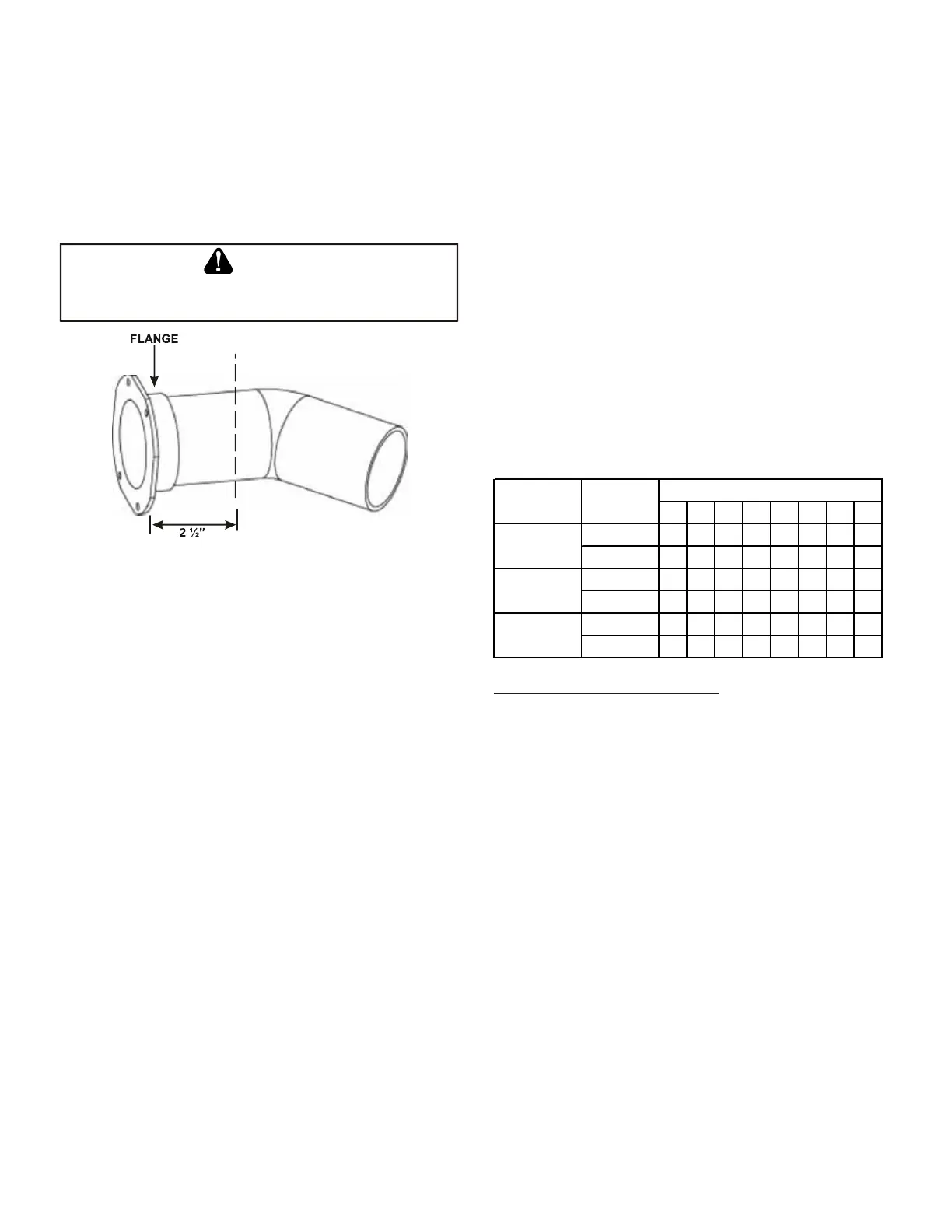
2. Remove the internal elbow and vent pipe
3. Cut 2 1/2" from the flange .
4. Remove plastic plug in line with the inducer outlet
5. Install cut end of the flanged section and connect
to inducer with rubber coupling supplied with
furnace.
6. Install screws removed in step 1 securing flange to
cabinet.
B
E
SURE
NOT
TO
DAMAGE
INTERNAL
WIRING
OR
OTHER
COMPONENTS
WHEN
REINSTALLING
COUPLING
AND
SCREWS
.
WARNING
C
U
T
H
E
R
E
Figure 10
Vent/Flue Pipe Cuts
ALTERNATE COMBUSTION AIR PROVISION
(Upflow / Horizontal models only)
When using the alternate venting location, either in a hori-
zontal left side down installation or a vertical installation
using down – venting, an alternate combustion air opening
can be used. A locating dimple is located on the right side of
the furnace cabinet. The locating dimple is 1 7/8" mea-
sured from the front edge of the cabinet in line with the
knock out. To use the alternate combustion air location:
1. Remove screws and combustion air flange from
cabinet.
2. Insert cabinet plug in unused combustion air hole.
3. Drill a pilot hole at the cabinet dimple (size dictated
by knockout tool used).
4. Use a knockout tool to create a 3" diameter hole
5. Install combustion air flange and secure with screws
removed in step one.
NON-DIRECT VENT (SINGLE PIPE) PIPING
Non-direct vent installations require only a vent/flue pipe. The
vent pipe can be run horizontally with an exit through the side of
the building or run vertically with an exit through the roof of the
building. The vent can also be run through an existing unused
chimney; however, it must extend a minimum of 12 inches above
the top of the chimney. The space between the vent pipe and the
chimney must be closed with a weather-tight, corrosion-resis-
tant flashing.
Although non-direct vent installations do not require a com-
bustion air intake pipe, a minimum of one 90° elbow should
be attached to the furnace’s combustion air intake if: an up-
right installation uses the standard intake location, or a hori-
zontal installation uses the alternate air intake location. This
elbow will guard against inadvertent blockage of the air in-
take.
VENT/FLUE PIPE LENGTHS AND DIAMETERS
NOTE: If either a 90 degree or 45 degree elbow is used for
termination, it must be pointed downward.
Refer to the Direct and Non-Direct Vent Table for applicable
length, elbows, and pipe diameter for construction of the vent/
flue pipe system of a non-direct vent installation. In addition to
the vent/flue pipe, a single 90° elbow should be secured to the
combustion air intake to prevent inadvertent blockage. The tee
used in the vent/flue termination must be included when deter-
mining the number of elbows in the piping system.
Max Allowable Vent Length of Vent/Flue Pipe & Combustion
Air Pipe (Ft)
12345678
2 9590858075706560
3 103 96 89 82 75 68 61 54
2 9085807570656055
3 158 151 144 137 130 123 116 109
2 5550454035302520
3 151 144 137 130 123 116 109 102
*MES960403BN
*MES960603BN
*MES960805CN
MODEL Pipe Size (in)
Number of Elbows
4500 ft altitude and above use 3” pipe
VENT/FLUE PIPE TERMINATIONS
NOTE: If either a 90 degree or 45 degree elbow is used for
termination, it must be pointed downward.
The vent/flue pipe may terminate vertically, as through a roof,
or horizontally, as through an outside wall.
Vertical vent/flue pipe terminations should be as shown in
the following figure. Refer to Vent/Flue Pipe and Combustion
Air Pipe - Termination Locations for details concerning loca-