23
Natural Gas Capacity of Pipe
In Cubic Feet of Gas Per Hour (CFH)
Length of Nominal Black Pipe Size
Pipe in Feet 1/2" 3/4" 1" 1 1/4" 1 1/2"
10 132 278 520 1050 1600
20 92 190 350 730 1100
30 73 152 285 590 980
40 63 130 245 500 760
50 56 115 215 440 670
60 50 105 195 400 610
70 46 96 180 370 560
80 43 90 170 350 530
90 40 84 160 320 490
100 38 79 150 305 460
(Pressure 0.5 psig or less and pressure drop of 0.3" W.C.; Based on
0.60 Specific Gravity Gas)
CFH =
BTUH Furnace Input
Heating Value of Gas (BTU/Cubic Foot)
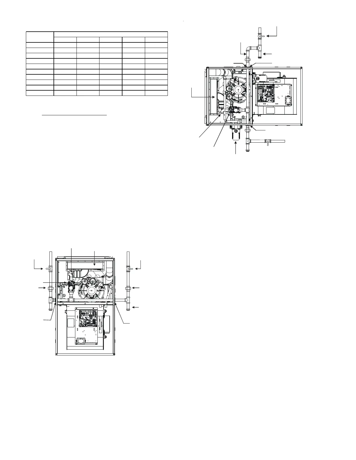
The gas piping may enter the left or right side of the
furnace cabinet. The installer must supply rigid pipe long
enough to reach the outside of the cabinet to seal the grom-
met cabinet penetration. A semi-rigid connector to the gas
piping can be used outside the cabinet per local codes. 1/2”
NPT pipe and fittings are required. For models with an
“L” shaped manifold, a 4 1/2” long nipple is required.
For models with a hook shaped manifold, a 2” long nipple
is required.
A semi-rigid connector to the gas piping can be used out-
side the cabinet per local codes. From the elbow, the length
of pipe and the fittings required will vary by the side cho-
sen, location of union and cabinet width. The union may
be placed inside or outside of the cabinets.
Alternate
Gas Line
Location
Plug in
Alternate
Gas Line
Hole
* Ground
Joint
Pipe
Union
Gas Valve
*Ground
Joint
Pipe
Union
Manual Shut Off Valve
(upstream from
ground joint
pipe union)
Grommet
in Standard
Gas Line
Hole
Drip Leg
Burners
Manifold
* NOTE: Union may be inside furnace cabinet where allowed by local codes.
UPFLOW
Figure 27
Manual Shut Off Valve
(upstream from
ground joint pipe union)
Drip Leg
Plug in Alternate Gas Line Hole
Grommet in
Standard Gas Line Hole
Alternate
Union
Location
Burners
Drain Trap
Gas Valve
Plug in Main Gas Line Hole
Manifold
UPFLOW - HORIZONTAL LEFT
Figure 28
GAS PIPING CHECKS
Before placing unit in operation, leak test the unit and gas con-
nections.
Check for leaks using an approved chloride-free soap and water
solution, an electronic combustible gas detector, or other ap-
proved testing methods.
NOTE: Never exceed specified pressures for testing. Higher
pressure may damage the gas valve and cause subsequent
overfiring, resulting in heat exchanger failure.
Disconnect this unit and shutoff valve from the gas supply piping
system before pressure testing the supply piping system with
pressures in excess of 1/2 psig (3.48 kPa).
Isolate this unit from the gas supply piping system by closing its
external manual gas shutoff valve before pressure testing supply
piping system with test pressures equal to or less than 1/2 psig
(3.48 kPA).
C
IRCULATING
A
IR
& F
ILTERS
DUCT WORK - AIR FLOW
Duct systems and register sizes must be properly designed for
the CFM and external static pressure rating of the furnace. De-
sign the ductwork in accordance with the recommended meth-
ods of “Air Conditioning Contractors of America” Manual D.
Install the duct system in accordance with Standards of the Na-
tional Board of Fire Underwriters for the Installation of Air Condi-
tioning, Warm Air Heating and Ventilating Systems. Pamphlets
No. 90A and 90B.
 Loading...


