34
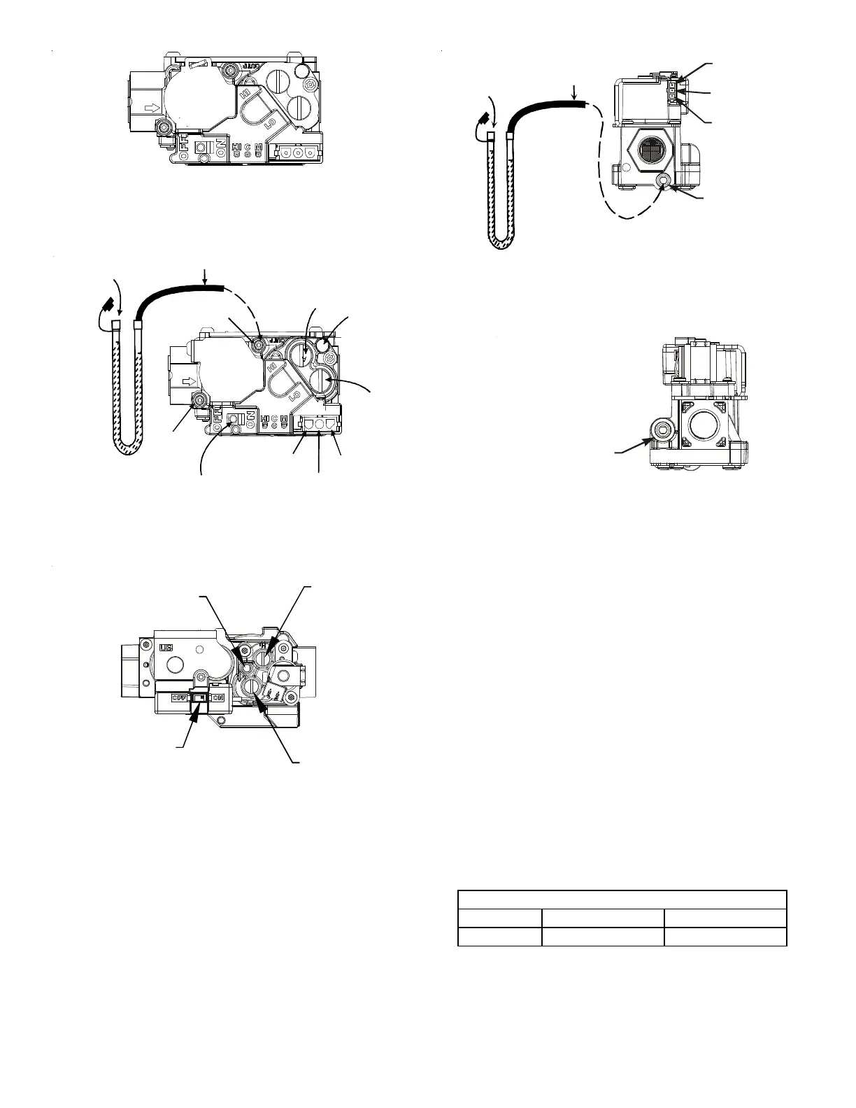
White-Rodgers Model 36J54 (Two-Stage)
Figure 46A
Inlet
Pressure
Boss
Low Fire
Regulator
Adjust
M
a
n
o
m
e
t
e
r
M
a
n
o
m
e
t
e
r
H
o
s
e
High Fire Regulator
Adjust
Regulator
Vent
Outlet
Pressure Boss
Open to
Atmosphere
O
n
/
O
f
f
S
w
i
t
c
h
H
i
g
h
F
i
r
e
C
o
i
l
T
e
r
m
i
n
a
l
(
H
I
)
C
o
a
x
i
a
l
C
o
i
l
T
e
r
m
i
n
a
l
(
M
)
Common
Terminal(C)
White-Rodgers Model 36J54 Connected to Manometer
Figure 46B
Gas Valve On/Off
Selector Switch
Regulator
Vent
Low Fire
Regulator
Adjust
High Fire
Regulator
Adjust
Honeywell Model VR9205 (Two-Stage)
Figure 47A
i
M
a
n
o
m
e
t
e
r
M
a
n
o
m
e
t
e
r
H
o
s
e
Common
Terminal(C)
High Fire Coil
Terminal (HI)
Low Fire Coil
Terminal (LO)
Inlet Pressure Tap
1/8 NPT
O
p
e
n
t
o
A
t
m
o
s
p
h
e
r
e
Honeywell Model VR9205 Connected to Manometer
Figure 47B
Outlet Pressure Tap
1/8 NPT
Figure 47C
NOTE: If measuring gas pressure at the drip leg or Honeywell
VR9205 gas valve, a field-supplied hose barb fitting must be
installed prior to making the hose connection. If using the
inlet pressure tap on the White-Rodgers 36J54 gas valve,
then use the 36G/J Valve Pressure Check Kit, Part No.
0151K00000S.
3. Turn ON the gas supply and operate the furnace and all
other gas consuming appliances on the same gas supply
line.
4. Measure furnace gas supply pressure with burners firing.
Supply pressure must be within the range specified in the
Inlet Gas Supply Pressure table.
If supply pressure differs from table, make the necessary
adjustments to pressure regulator, gas piping size, etc., and/
or consult with local gas utility.
5. Turn OFF gas to furnace at the manual shutoff valve and
disconnect manometer. Reinstall plug before turning on
gas to furnace.
6. Turn OFF any unnecessary gas appliances stated in step
3.
Natural Gas Minim um : 4.5" w.c. Maxim um : 10.0" w.c.
Propane Gas Minimum: 11.0" w.c. Maximum: 13.0" w.c.
INLET GAS SUPPLY PRESSURE