40
Typical 18 AWG thermostat wire may be used to wire the
system components. One hundred (100) feet is the maximum
length of wire between indoor unit and outdoor unit, or
between indoor unit and thermostat. Wire runs over (100)
feet require larger gauge wire.
FOUR-WIRE INDOOR AND OUTDOOR WIRING
Typical ComfortNet wiring will consist of four wires between
the indoor unit and outdoor unit and between the indoor unit
and thermostat. The required wires are: (a) data lines, 1
and 2; (b) thermostat “R” (24 VAC hot) and “C” (24 VAC
common).
12RC
12RC
CTK0*
Thermostat
ComfortNet Compatible Furnace
Integrated Control Module
ComfortNet Compatible AC/HP
Integrated Control Module
12RC
System Wiring using Four-Wires
Figure 54
TWO-WIRE OUTDOOR, FOUR-WIRE INDOOR WIRING
Two wires can be utilized between the indoor and outdoor
units. For this wiring scheme, only the data lines, 1 and 2,
are needed between the indoor and outdoor units. A 40VA,
208/230 VAC to 24VAC transformer must be installed in the
outdoor unit to provide 24VAC power to the outdoor unit’s
electronic control. See instruction manual provided with the
thermostat for wiring instructions.
NOTE: Use of a transformer is recommended if installing a
dual fuel/fossil fuel system with a CTK01* or CTK02*. Fail-
ure to use the transformer in the outdoor unit could result in
over loading of the furnace transformer. Follow the thermo-
stat manufacturers recommendation on when an outdoor
transformer is needed. Do not attempt to install an outdoor
transformer when using an inverter type unit.
12RC
12RC
CTK0*
Thermostat
ComfortNet Compatible
Furnace Integrated
Control Module
ComfortNet Compatible
AC/HP Integrated
Control Module
40VA Transformer
208/230 VAC
24 VAC
12RC
System Wiring using Two-Wires between Furnace and AC/HP and Four-Wires
Between Furnace and Thermostat
Figure 55
COMFORTNET™ COMPATIBLE FURNACE WITH NON-COMFORTNET
COMPATIBLE
SINGLE-STAGE AIR CONDITIONER
Four wires are required between the furnace and thermostat.
Two wires are required between the furnace control and single
stage air conditioner. For this system configuration, the
“Y1” terminal on the integrated furnace control becomes an
output rather than an input. The “Y1” connection to the
outdoor unit is made using both 4-position thermostat
connectors in the CTK0* kit. Remove the red keying tabs
from the on-board connector block and position both 4-
position connector such that “1”, “2”, “R”, “C”, and “Y1”
positions are filled.
NOTE: The cooling CFM for this installation must be set up
at the communicating thermostat through ComfortNet
>furnace menu > non com menu
12RC
C Y
ComfortNet Compatible
Furnace Integrated
Control Module
CTK0*
Thermostat
Non- Compatible
Single Stage AC
ComfortNet
G
W1 W2 Y1 Y2
O
12RC
4-Position Connectors
from CTK0*
Thermostat Kit
System Wiring between Furnace and Non-Communicating Compatible
Single Stage Air Conditioner
Figure 56
COMFORTNET SYSTEM ADVANCED FEATURES
The ComfortNet system permits access to additional system
information, advanced setup features, and advanced
diagnostic/troubleshooting features. These advanced
features are organized into a menu structure. The menus
are accessed and navigated by means of the CTK0*
thermostat. For details, see the thermostat instruction
manual.
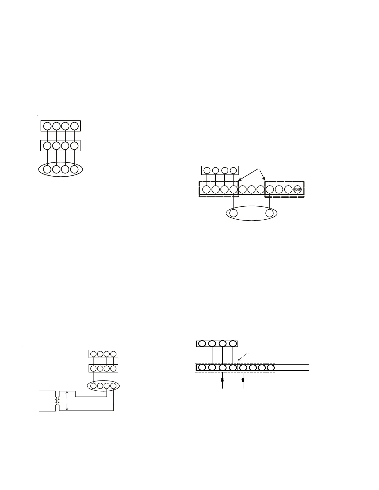
W1 W2 Y1 Y2 O DEHUM
24 vac "G" input to Furnace
Integrated Control module From
ERV / HRV or Similar Devices
1
1
2RC
2
Furnace Integrated
Control Module
RC
G
CTK0* Thermostat
4-Pin (X2), 7 Pin, or 9 Pin Connector
NOTE: PCBKF105 IFC has the added feature of 24 VAC input
to G terminal when using a communicating thermostat. ERV/
HRV and other accessories can send a signal to the G terminal
and energize the continuous fan. The continuous fan speed
can be adjusted on switch bank S5, dip switch 3 & 4. The 24
vac source must originate from the R terminal of furnace.