38
8. Select the desired “heating” speed tap by positioning
switches S4- 3,4 appropriately. Refer to figure above.
Verify CFM by noting the number displayed on the dual 7-
segment LED display.
34
AOFFOFF
B* ON OFF
COFFON
DONON
(Indicates factory setting)
Sw itch Bank S4
Heating
Airflow
DIP Sw itc h No.
In general lower heating speeds will: reduce electrical
consumption, lower operating sound levels of the blower,
and increase the outlet air temperature delivered to the
home. The speeds available allow the blower performance
to be optimized for the particular homeowner’s needs.
Continuous fan speeds that provide 25, 50, 75 and 100% of
the furnace’s maximum airflow capability are selectable via
dip switches S5- 3, 4.
Example: If the furnace’s maximum airflow capability is
2000 CFM and 25% continuous fan speed
is selected, the continuous fan speed will
be 0.25 x 2000 CFM = 500 CFM.
BLOWER HEAT OFF DELAY TIMINGS
The integrated control module provides a selectable heat
off delay function. The heat off delay period may be set to
90, 120, 150, 180 seconds using the DIP switches or jumper
provided on the control module. The delay is factory shipped
at 150 seconds but may be changed to suit the installation
requirements and/or homeowner preference. Refer to the
following figures for switch positions and corresponding delay
times.
12
90 seconds OFF OFF
120 seconds ON OFF
150 seconds* OFF ON
180 seconds ON ON
Heat Off Delay Dip Switches
(*Indicates factory setting)
Heat OFF Delay
DIP Sw itc h No.
Sw itch Bank : S1
C
OMFORT
N
ET
™ S
YSTEM
OVERVIEW
The ComfortNet system is a system that includes a
ComfortNet compatible furnace and air conditioner or heat
pump with a CTK0* thermostat. A valid ComfortNet system
could also be a compatible furnace, CTK0* thermostat and
non-compatible, single stage air conditioner. Any other
system configurations are considered invalid ComfortNet
systems and must be connected as a traditional (or non-
communicating) system (see Electrical Connections for wiring
connections).
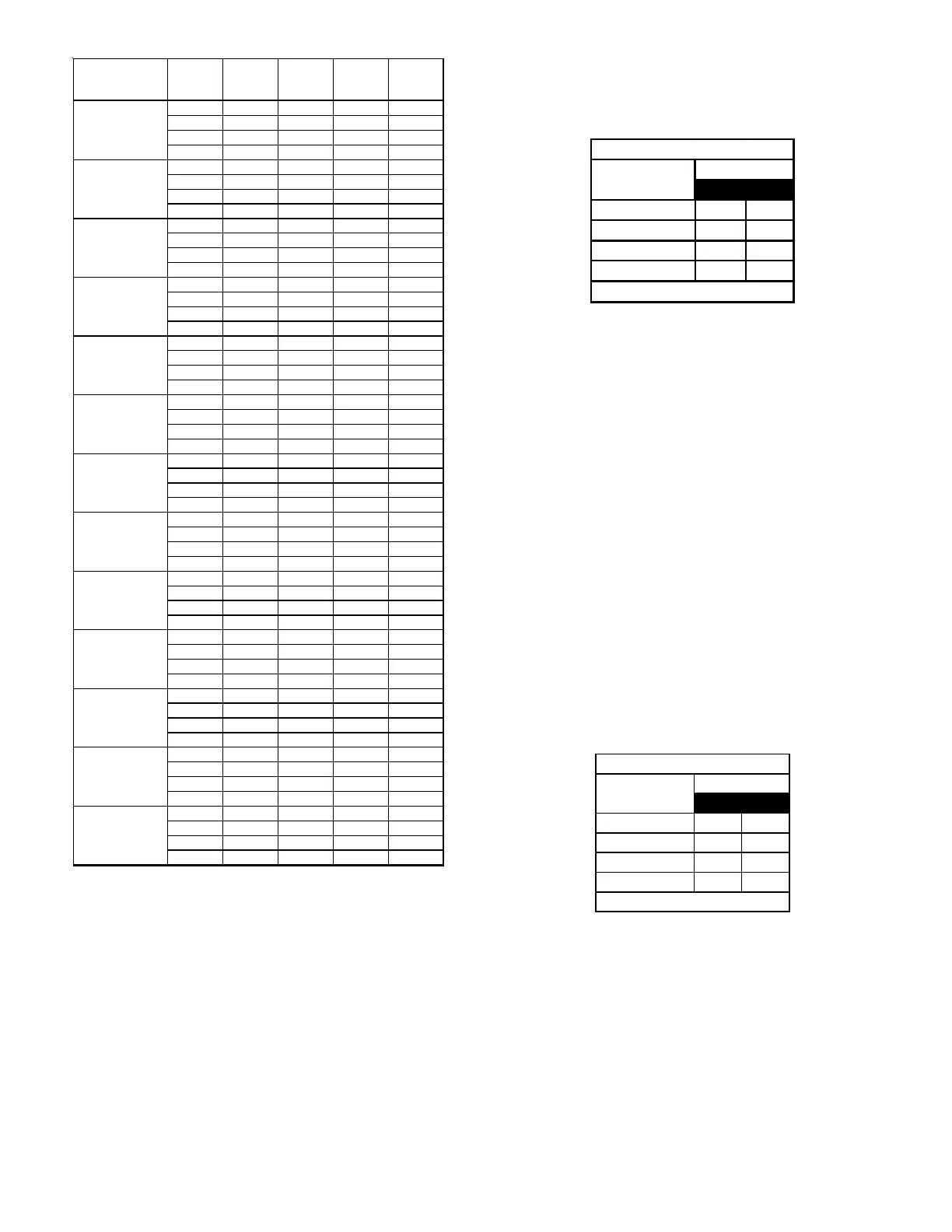
Model Tap
Low
Stage
Cool
High
Stage
Cool
Low Stage
Heat
High
Stage
Heat
A
403 596 422 494
B
527 796 471 553
C
675 974 521 601
D
803 1192 574 676
A
398 599 667 953
B
557 817 740 1059
C
696 1007 808 1158
D
810 1212 881 1260
A
403 629 855 1202
B
540 806 923 1316
C
705 1023 1033 1389
D
819 1230 1063 1396
A
513 789 867 1228
B
660 967 939 1337
C
791 1182 1016 1430
D
913 1375 1077 1516
A
564 820 1256 1818
B
784 1133 1292 1870
C
982 1464 1316 1910
D
1259 1736 1358 1957
A
597 895 1205 1683
B
852 1156 1230 1727
C
1031 1459 1256 1763
D
1282 1864 1281 1796
A
547 867 1329 1891
B
831 1160 1362 1940
C
1020 1467 1390 1968
D
1278 1910 1440 2028
A
449 655 682 957
B
569 807 750 1059
C
716 998 820 1155
D
854 1207 888 1251
A
433 656 687
938
B
541 790 751
950
C
686 972 814 986
D
806 1195 874 992
A 405 624 758 1057
B 549 808 815 1146
C 678 994 882 1256
D 784 1177 946 1349
A
556 837 889 1234
B
714 1022 944 1325
C
838 1206 1019 1442
D
991 1475 1068 1528
A
524 784 1209 1759
B
744 1078 1249 1797
C
927 1388 1277 1840
D
1185 1766 1300 1881
A
540 854 1284 1744
B
870 1123 1310 1827
C
1000 1399 1350 1860
D
1235 1804 1388 1918
DC96VC1205DN*
DM96VC1205DN*
DC96VC0603BN
DC96VC0803BN
DC96VC0804CN*
DM96VC0603BN*
DM96VC0803BN*
DM96VC0804CN*
DM96VC1005CN*
DM96VC1005DN*
DC96VC1005CN*
DM96VC0403BN*
DC96VC0403BN*
Airflow Table
7. Select the heating speed for your model from the heating
speed chart in the Specification Sheet. The adjust setting
(already established by the cooling speed selection)
determines which set of speeds are available. The selected
speed must provide a temperature rise within the rise
range listed with the particular model.
Example: If the DM96VC0804CN** is set for 1210 CFM
on cooling, the “ADJUST” is set to “+” (plus).
The four heating speeds available are “A
Plus”, “B Plus”, “C Plus”, and “D Plus”. “A
Plus” has a rise of 46°F for both stages which
is within the 30-60°F rise range for the
DM96VC0804CN**. This setting will keep
electrical consumption to a minimum. Set
the “Heat” speed DIP switches to “A”.