DPS 003–015 (only) Ignition Control Module for Staged Gas Furnace
Figure 52: Typical Staged Gas Furnace Electrical Schematic with Sensor
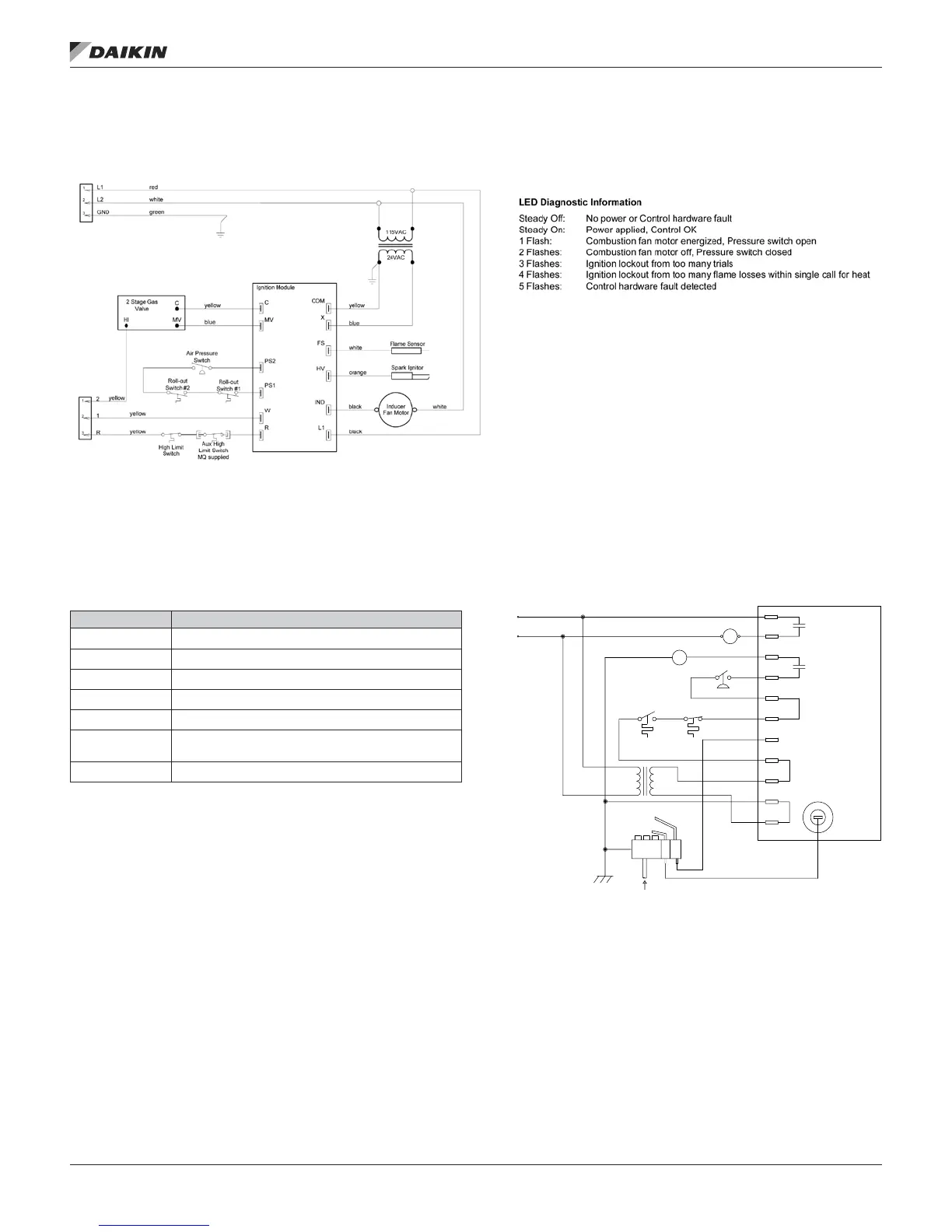
Ignition Control Module LED Diagnostics
The following LED indicators can be used to diagnose faults
associated with the staged gas furnace.
Table 21: LED Indicator and Fault Conditions
Indicator Fault Condition
Steady Off No power or control hardware fault
Steady On Power applied, control OK
1 Flash Combustion fan motor energized, pressure switch open
2 Flashes Combustion fan motor off, pressure switch closed
3 Flashes Ignition lockout from too many trials
4 Flashes
Ignition lockout from too many ame losses within single
call for heat
5 Flashes Control hardware fault detected
Figure 53: Ignition Control Wiring
GAS
SYSTEM WIRING DIAGRAM
SENSE
SPARK
VOLTAGE
HIGH
24VAC
120VAC
MAIN
GAS VALVE
INDUCER
PRESSURE SWITCH
PSI
T'STAT
LIMIT
COM
C
X
R
FS
W
PS2
IND
L1
BURNER
MV
120/240 VAC
1016-4XX
FOR CONTROL WITH POST-PURGE
IM 1125-7 • REBEL ROOFTOPS 52 www.DaikinApplied.com
opTIonal gas heaT