Our continuing commitment to quality products may mean a change in specications without notice.
© 2015-2019
5151 San Felipe St., Suite 500, Houston, TX 77056
www.daikincomfort.com
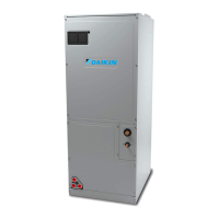
DV**PEC / DV**FEC (EEV SERIES AIR HANDLERS)
IOD-4018J
11/2019
INSTALLATION INSTRUCTIONS
1 Important Safety Instructions ............................................................... 2
2 Shipping Inspection ...............................................................................3
2.1 Parts ........................................................................................................3
2.2 Handling ..................................................................................................3
3 Codes & Regulations ............................................................................. 3
4 Replacement Parts.................................................................................3
5 Pre-Installation Considerations ........................................................... 3
5.1 Preparation .............................................................................................. 3
5.2 System Matches ...................................................................................... 3
5.3 Interconnecting Tubing ............................................................................ 3
5.4 Clearances ..............................................................................................3
5.5 Horizontal Applications ............................................................................3
6 Installation Location ............................................................................. 4
6.1 Upow Installation ................................................................................... 4
6.2 Horizontal Left Installation ....................................................................... 4
6.3 Downow/Horizontal Right Installation .................................................... 4
7 Refrigerant Lines ................................................................................... 7
7.1 Tubing Size .............................................................................................. 7
7.2 Tubing Preparation .................................................................................. 7
7.3 Tubing Connections ................................................................................. 8
8 Condensate Drain Lines ........................................................................ 8
9 Ductwork.................................................................................................9
9.1 Return Ductwork ...................................................................................... 9
10 Return Air Filters ..................................................................................9
11 Electric Heat ......................................................................................... 9
12 Electrical and Control Wiring ............................................................ 11
12.1 Building Electrical Service Inspection .................................................. 11
12.2 Wire Sizing .......................................................................................... 11
12.3 Maximum Overcurrent Protection (MOP) ............................................ 11
12.4 Electrical Connections – Supply Voltage ............................................. 11
12.4.1 Air Handler Only (Non-Heat Kit Models) ........................................... 11
12.4.2 Air Handler - Non-Circuit Breaker Heat Kits ..................................... 11
12.4.3 Air Handler With Circuit Breaker Heat Kit ......................................... 11
13 Achieving 1.4% & 2% Low Leakage Rate ........................................ 12
14 Airow Trim ........................................................................................ 12
15 Miscellaneous Start-Up Checklist .................................................... 12
15.1 Auxiliary Alarm Switch .........................................................................13
15.2 Circulator Blower ................................................................................. 14
15.3 Motor Orientation ................................................................................. 14
15.4 Accessory Contacts ............................................................................. 14
16 Troubleshooting .................................................................................. 15
16.1 Electrostatic Discharge (ESD) Precautions ....................................... 15
16.2 Diagnostic Chart ................................................................................. 15
16.3 Fault Recall.........................................................................................15
17 Fully Communicating Daikin System ................................................ 16
17.1 Overview..............................................................................................16
17.2 Airow Consideration ...........................................................................16
17.3 Thermostat Wiring ...............................................................................16
17.3.1 Two-Wire Outdoor and Four-Wire Indoor Wiring ......................... 16
17.4 Network Troubleshooting ..................................................................... 16
17.5 System Troubleshooting ...................................................................... 17
Troubleshooting ........................................................................................ 18
Diagnostic Codes ......................................................................................21
Setting the mode display .......................................................................... 22
Wiring Diagram .......................................................................................... 24
Routine Maintenance ................................................................................ 25
NOTICE
If an “Ed” error is encountered
on startup, verify that the
electric heater DIP switches
have been set to the appropriate
heater size. See Tables 9 and 10
for the heater kit airow delivery
and DIP switch settings.
Only personnel that have been trained to install, adjust, service or
repair (hereinafter, “service”) the equipment specified in this manual
should service the equipment. The manufacturer will not be
responsible for any injury or property damage arising from improper
service or service procedures. If you service this unit, you assume
responsibility for any injury or property damage which may result. In
addition, in jurisdictions that require one or more licenses to service
the equipment specified in this manual, only licensed personnel
should service the equipment. Improper installation, adjustment,
servicing or repair of the equipment specified in this manual, or
attempting to install, adjust, service or repair the equipment specified
in this manual without proper training may result in product damage,
property damage, personal injury or death.
RECOGNIZE THIS SYMBOL
AS A SAFETY PRECAUTION.
Cancer and Reproductive Harm -
www.P65Warnings.ca.gov
PROP 65 WARNING
FOR CALIFORNIA CONSUMERS
0140M00517-A


 Loading...