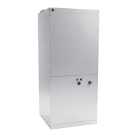
DV**PTC*14 SERIES AIR HANDLERS
IOD-4021K
06/2021
Only personnel that have been trained to install, adjust, service
or repair (hereinafter, “service”) the equipment specified in
this manual should service the equipment. The manufacturer
will not be responsible for any injury or property damage
arising from improper service or service procedures. If you
service this unit, you assume responsibility for any injury or
property damage which may result. In addition, in jurisdictions
that require one or more licenses to service the equipment
specified in this manual, only licensed personnel should service
the equipment. Improper installation, adjustment, servicing
or repair of the equipment specified in this manual, or
attempting to install, adjust, service or repair the equipment
specified in this manual without proper training may result in
product damage, property damage, personal injury or death.
INSTALLATION INSTRUCTIONS
www.daikincomfort.com
Our continuing commitment to quality products may mean a change in specications without notice.
19001 Kermier Road Waller, TX 77484
Index
1 Important Safety Instructions ................................................................ 2
2 Shipping Inspection ............................................................................... 3
2.1 Parts ............................................................................................... 3
2.2 Handling .......................................................................................... 3
3 Codes & Regulations ............................................................................. 3
4 Replacement Parts ................................................................................. 3
5 Pre-Installation Considerations ............................................................ 3
5.1 Preparation ..................................................................................... 3
5.2 System Matches ............................................................................. 3
5.3 Interconnecting Tubing ................................................................... 4
5.4 Clearances ...................................................................................... 4
5.5 Horizontal Applications ................................................................... 4
6 Installation Location ......................................................... 4
6.1 Upow Installation ........................................................................... 4
6.2 Horizontal Left Installation .............................................................. 4
6.3 Downow/Horizontal Right Installation ........................................... 4
7 Refrigerant Lines .................................................................................... 6
7.1 Tubing Size ..................................................................................... 6
7.2 Tubing Preparation ......................................................................... 6
7.3 Tubing Connections for TXV Models .............................................. 7
7.4 Thermal Expansion Valve System Adjustment ............................... 8
8 Condensate Drain Lines .................................................. 8
9 Ductwork ......................................................................... 10
9.1 Thermal Expansion Valve System Adjustment ...................................... 10
10 Return Air Filters .................................................................................. 10
11 Electric Heat .......................................................................................... 10
12 Electrical and Control Wiring ..............................................................11
12.1 Building Electrical Service Inspection ..........................................11
12.2 Wire Sizing ...................................................................................11
12.3 Maximum Overcurrent Protection (MOP) ....................................11
12.4 Electrical Connections – Supply Voltage .................................... 12
12.4.1 Air Handler Only (Non-Heat Kit Models) .................................. 12
12.4.2 Air Handler - Non-Circuit Breaker Heat Kits ............................. 12
12.4.3 Air Handler With Circuit Breaker Heat Kit ................................ 12
12.5 Low Voltage Connections ........................................................... 12
13 Achieving 1.4% and 2.0% Airow Low Leakage Rate ......................11
14 Start-Up Procedure ............................................................................. 12
15 Regular Maintenance ......................................................................... 12
16 Circulator Blower ................................................................................ 15
17 Troubleshooting ................................................................................. 17
© 2014 - 2021
If an “Ec” error is encountered on
startup, verify that the electric heater
DIP switches have been set to the
appropriate heater size. See pages
14-17 for the heater kit airflow
delivery and DIP switch se�ngs.