Do you have a question about the Daikin DAX Series and is the answer not in the manual?
Disconnect all power before servicing. Multiple power sources may be present. Risk of injury or death.
Unit must have an uninterrupted electrical ground per NEC/CSA codes to prevent shock, injury, or death.
Risk in enclosed areas with CO devices. Requires adequate ventilation to prevent illness or death.
Recommend safety clothing during installation/servicing. Observe site-specific safety requirements.
Use only manufacturer-approved devices. Non-approved devices risk damage, poor performance, or hazards.
Do not store flammable liquids or vapors near the unit to prevent damage, injury, or death.
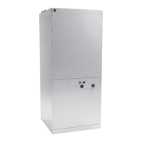
Identifies unit model (DAX) and nominal cooling capacity (e.g., 7.5 Ton, 10 Ton).
Inspect unit for damage upon delivery. Verify model and voltage against requirements.
System complies with ASHRAE 90.1-2019 when matched with specific condensers. Requires 24 VAC thermostat.
Details weight, refrigerant, blower, coil material, line sizes, and metering device.
Installation must comply with codes. Order replacement parts using model/serial numbers.
Read all instructions, understand procedures, and gather necessary tools and supplies before starting.
Unit is for indoor use only. Ensure proper ventilation and adequate service clearance.
Size ductwork for airflow (375-425 CFM/ton) and limit external static pressure to 0.5" WC.
Attach supply ductwork flanges. Do not introduce fumes into return ductwork.
Install filters and replace them frequently for optimal performance. Filter sizes are listed.
AHKD series kits are accessories. Lists models, KW, voltage, phase, and stages.
Tables provide correction factors for various voltages to adjust KW or temperature rise.
Show temperature rise based on KW, CFM, and voltage for DAX0904 and DAX1204.
Use copper conductors. Follow wire sizing and MOP requirements. High voltage warnings apply.
Requires 3-phase power. Supply voltage must match unit nameplate and be within range.
Formula to calculate voltage unbalance (phase to phase), which must be within 2%.
Select wire size for MCA and 2% voltage drop. Maximum allowable length table provided.
Install NEC/CEC approved overcurrent protection sized for MCA but not exceeding MOP.
Use copper conductors. Connect to control box single point termination as per diagram.
Shows supply voltage hook-up for units without a heat kit, using conduit to unit knockout.
Connects supply voltage to heater kit terminal block and low voltage via multi-pin plug.
24V control connects air handler to thermostat/condenser. Use minimum 18AWG copper wire.
Inspect heat kit for damage and verify model, size, and electrical specs on the nameplate.
Use heat shield or wet rags to protect unit finish and sensitive components during brazing.
Ensure clean, burr-free ends. Quench welded joints with water or a wet rag.
Follow condenser/heat pump specifications for correct suction and liquid line tubing sizes.
Manifold lines for single condenser. Specific procedures shown for two outdoor units.
Attach TXV bulb to suction line after brazing, typically at 10 or 2 o'clock position.
Unit has 5 speed settings (T1-T5). Select speed based on installation requirements.
Lists descriptions for each speed tap. Change settings by moving wires to desired tap.
The only user-maintained item is the air filter. Clean or replace regularly.
Technicians should check filters, clean coils, inspect ducts, check refrigerant charge and leaks.
Provides SCFM, RPM, and BHP for DAX0904 in upflow and horizontal configurations across speed taps.
Provides SCFM, RPM, and BHP for DAX1204 in upflow and horizontal configurations across speed taps.
Diagram for DAX 090-120, 3PH power and controls, including notes on wire types and connections.
Lists all components used in the diagram and their associated wire color codes.
Distinguishes between field and factory wiring connections and their respective labels.
System wiring diagram for DAX 090-120, 3PH showing field connections to thermostats and condensers.
Diagrams for connecting one 2-stage AC or Heat Pump unit to the thermostat.
Diagram illustrating connections for two 1-stage AC condenser units to the thermostat.
| Phase | 1 |
|---|---|
| Motor Type | ECM |
| Dimensions | Varies by model |
| Weight | Varies by model |
| Heating Capacity | 5 kW - 10 kW |