9
CAUTION
GROUNDING REQUIRED!
ALWAYS INSPECT AND USE PROPER SERVICE TOOLS. LACK
OF INSPECTION OR IMPROPER TOOLS MAY CAUSE EQUIPMENT
DAMAGE OR PERSONAL INJURY. ALL DISCONNECTED GROUND-
ING DEVICES MUST BE RECONNECTED BEFORE INSTALLING
OR SERVICING. MULTIPLE COMPONENTS OF THIS UNIT MAY
CONDUCT ELECTRICAL CURRENT; THESE ARE GROUNDED. IF
SERVICING THE UNIT, ANY DISCONNECTION OF GROUNDING
WIRES, SCREWS, STRAPS, CLIPS, NUTS OR WASHERS USED TO
COMPLETE THE GROUND MUST BE RETURNED TO THEIR ORIGI-
NAL POSITION AND PROPERLY FASTENED.
NOTICE
• NEVER INSTALL A PHASE-ADVANCING CAPACITOR. AS
THIS UNIT IS EQUIPPED WITH AN INVERTER, INSTALLING
A PHASE-ADVANCING CAPACITOR WILL NOT ONLY
DETERIORATE POWER FACTOR IMPROVEMENT EFFECT,
BUT ALSO MAY CAUSE CAPACITOR ABNORMAL HEATING
ACCIDENT DUE TO HIGH-FREQUENCY WAVES.
• DO NOT CHANGE THE SETTING OF THE PROTECTION
DEVICES. IF THE PRESSURE SWITCH, THERMAL SWITCH,
OR OTHER PROTECTION DEVICE IS SHORTED AND
OPERATED FORCIBLY, OR PARTS OTHER THAN THOSE
SPECIFIED BY DAIKIN ARE USED, FIRE OR EXPLOSION
COULD RESULT.
• DO NOT CONNECT THE GROUND WIRE TO GAS PIPES,
SEWAGE PIPES, LIGHTNING RODS, OR TELEPHONE
GROUND WIRES.
The heat pump unit rating plate lists pertinent electrical data
necessary for proper electrical service and overcurrent protec-
tion. Wires should be sized to limit voltage drop to 2% (max.)
from the main breaker or fuse panel to the condensing unit.
Consult the NEC, CEC, and all local codes to determine the
correct wire gauge and length.
Local codes often require a disconnect switch located near
the unit; do not install the switch on the unit.
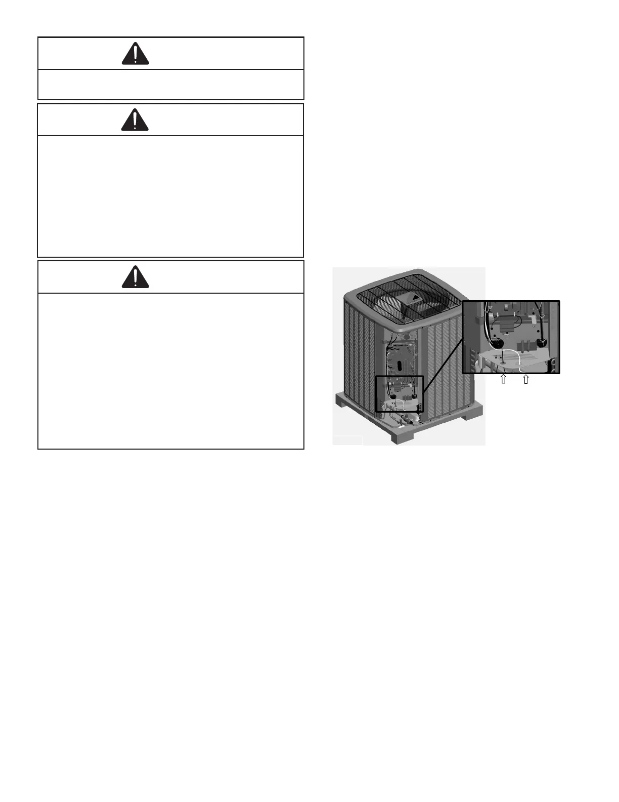
Route power supply and ground wires through the high volt-
age port and terminate in accordance with the wiring diagram
provided inside the control panel cover.
• Make sure to apply the rated voltage of 208/230V
for the unit.
• Use conduit for power supply cables.
• A power circuit (see the production specication
sheet or the unit serial plate) must be provided for
connection of the unit. This circuit must be protected
with the required safety devices.
• When using residual current operated circuit breakers,
be sure to use a high-speed type (0.1 seconds or less)
200 mA rated residual operating current.
• Use copper conductors only.
• Use insulated wire for the power cord.
• Select the power supply cable type and size
in accordance with relevant local and national
regulations.
• Outside the unit, make sure to keep the wirings 5 inch
away. Otherwise, the outdoor unit may be aected
by electrical noise (external noise), and malfunction
or fail.
• Make sure the wirings will not be pinched by the front
panel, and close the panel rmly.
• Route the conduit along the unit and so on to prevent
wirings from being stepped on.
The unit is designed to work as part of a fully communicating
HVAC system, utilizing a Daikin approved communicating
thermostat, communicating compatible indoor unit, and up to
four wires. Route control wires through the low voltage port
and terminate in accordance with the wiring diagram provided
inside the control panel cover.
Low Voltage
Port
High Voltage
Port
NOTE: The communicating thermostat is able to search and
identify the indoor and outdoor units when power is applied
to the system. Refer to the communicating thermostat’s in-
stallation instructions manual for more information.
Connect low voltage communication wires (1, 2) to low voltage
pigtail provided.
NOTE: A removable plug connector is provided with the
control board to make thermostat wire connections. This plug
may be removed, wire connections made to the plug, and
replaced. It is STRONGLY recommended that you do not
connect more than two wires into a single terminal in the eld
because there is a risk of the wires becoming loose. Failure
to do so may result in intermittent operation.
To wire the system components, it is strongly recommended to
use the same type and the same gauge for the wires prepared
in the eld (for best results use 18 AWG). However, commu-
nications reliability may be improved by using a high quality,
shielded, twisted pair cable for the data transmission lines.
WARNING
TO AVOID THE RISK OF FIRE OR EQUIPMENT DAMAGE, USE
COPPER CONDUCTORS.