10
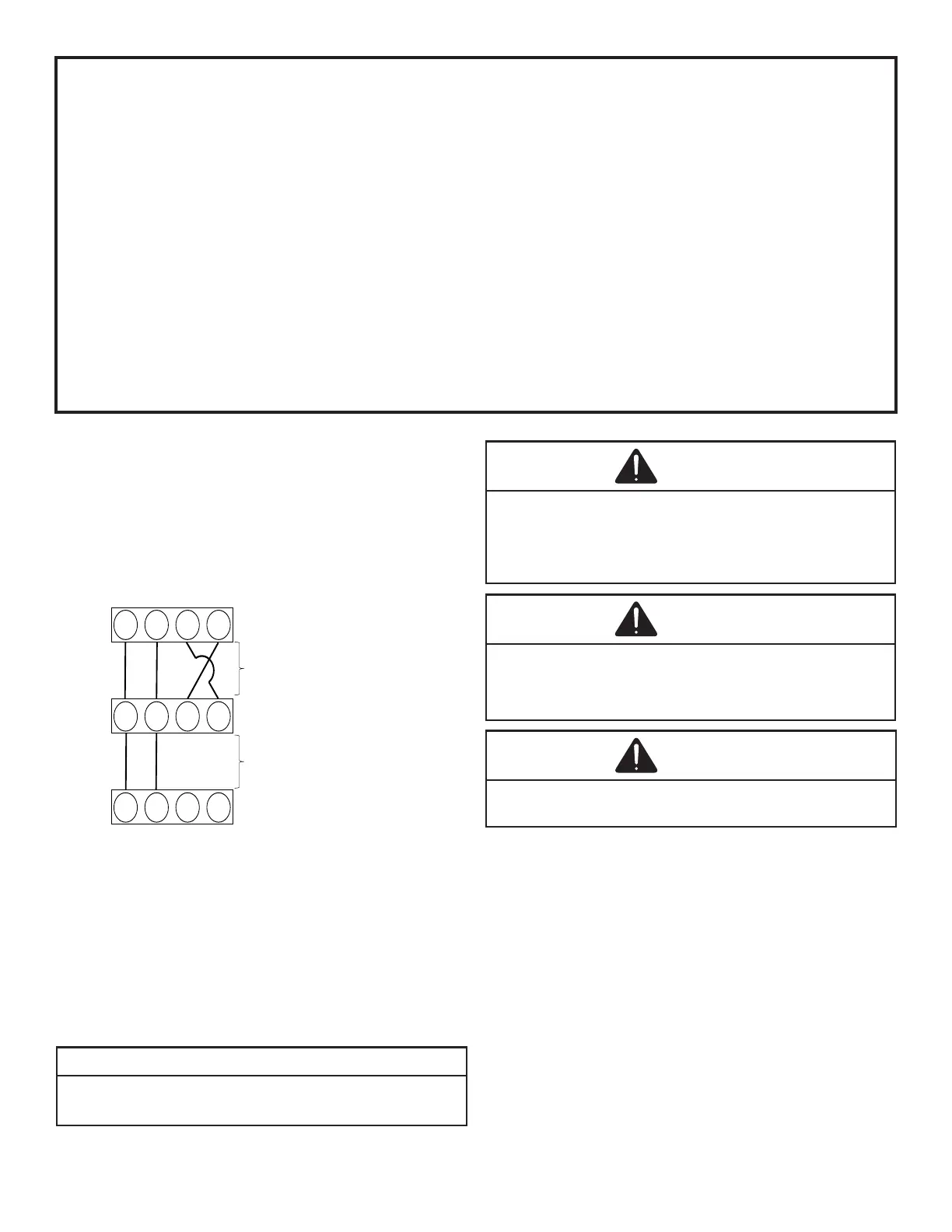
Typical wiring will consist of two wires between the indoor
unit and outdoor unit, and four wires between the indoor
unit and thermostat. The gure that follows shows the
required wires: Data lines, 1 and 2; “R” (24 VAC hot) and
“C” (24 VAC common).
Never connect the power wiring to communication terminal
1, 2, R, C)
1 2 C R
1
2 R
C
Air Handler Blower
Gas Furnace or Module Blower
Integrated Control Module
125 ft. (*)
(*) Allowable Maximum Length
Outdoor unit
Integrated Control Module
250 ft. (*)
1
2 R
C
Communicating Thermostat
( In case of DAIKIN ONE+
SMART THERMOSTAT)
The heat pump unit is shipped with a predetermined factory
charge level as shown in unit serial plate. For longer line
sets greater than 15 feet, add 0.6 ounces of refrigerant per
foot. Refer to the following page for the equivalent length of
elbow ttings.
NOTICE
TOTAL REFRIGERANT =
-
AL LINE SET).
CAUTION
OPEN THE LIQUID VALVE FIRST! IF THE SUCTION SERVICE
VALVE IS OPENED FIRST, OIL FROM THE COMPRESSOR MAY
BE DRAWN INTO THE INDOOR COIL TXV OR EEV RESTRICTING
REFRIGERANT FLOW AND AFFECTING OPERATION OF THE
SYSTEM.
CAUTION
POSSIBLE REFRIGERANT LEAK!
TO AVOID A POSSIBLE REFRIGERANT LEAK, OPEN THE SER-
VICE VALVES UNTIL THE TOP OF THE STEM IS 1/8” FROM THE
RETAINER.
CAUTION
ENSURE VALVES ARE OPEN AND ADDITIONAL CHARGE IS ADD-
ED PER CHART BEFORE APPLYING POWER.
Charge additional refrigerant calculated by STEP 1 formula
from liquid service valve (NOT from suction side).
After the refrigerant charge has bled into the system, open
the liquid service valve.
When opening valves with retainers, open each valve only
until the top of the stem is 1/8” from the retainer. To avoid loss
of refrigerant, DO NOT apply pressure to the retainer. When
opening valves without a retainer, remove service valve cap
and insert a hex wrench into the valve stem and back out the
stem by turning the hex wrench counterclockwise. Open the
valve until it contacts the rolled lip of the valve body.
The service valve cap is the secondary seal for the valves and
must be properly tightened to prevent leaks. Make sure cap is
clean and apply refrigerant oil to threads and sealing surface
on inside of cap. Tighten cap nger-tight and then tighten
additional 1/6 of a turn to properly seat the sealing surfaces.
ATTENTION INSTALLER - IMPORTANT NOTICE!
Please read carefully before installing this unit.
• Low voltage terminal C from indoor unit must connect to low voltage terminal C on thermostat and low voltage
terminal R on thermostat. Verify wires are not reversed. NOTE: The order of the terminals of the indoor unit and the
Only the data lines, 1 and 2, are required between the indoor and
outdoor units.
• Data line terminal #1 from outdoor unit must connect to terminal #1 on indoor unit and thermostat and data line
terminal #2 from outdoor unit must connect to terminal #2 on indoor unit and thermostat. Verify wires are not
reversed.
Or
• Charge by Sub-cooling.
Sub-cooling should be 8°F ±
 Loading...