11
Break vacuum by fully opening liquid and suction base valve.
NOTE: Units may utilize ball valves or front seating valves.
These are not back-seating valves. It is not necessary to force
the stem tightly against the rolled lip.
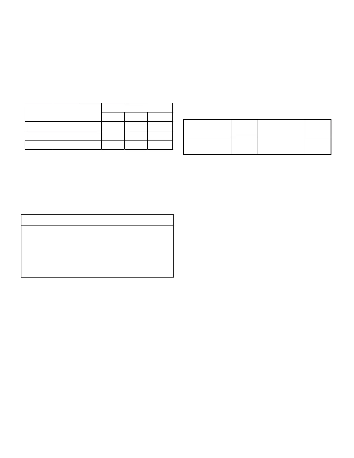
NOTE: The following table lists the equivalent length gained
from adding bends to the suction line. Properly size the suc-
tion line to minimize capacity loss.
1.7 2 2.3
1.5 1.7 1.6
0.7 0.8 1
For a detailed procedure, please visit the Daikin One+ Smart
Thermostat website at http://www.daikinone.com.
Using service equipment, add or recover refrigerant according
to the calculation in Step 1. Allow system to stabilize for 20
minutes after adjusting charge level.
NOTICE
WHEN PUT INTO CHARGE MODE THE 7-SEGMENT DISPLAY
WILL BEGIN BLINKING “CHA” LIGHTS. ONCE THE SYSTEM IS
STABLE THE “CHA” LIGHTS WILL STOP BLINKING AND STAY
EQUIPMENT, ADD OR RECOVER REFRIGERANT ACCORDING
TO THE CALCULATION IN STEP 1.
DO NOT ADJUST REFRIGERANT LEVEL IF THE “CHA” LIGHTS
ARE NOT SOLID.
NOTE: Charging equipment must use dedicated PVE oil
gauges and hoses.
1. Purge gauge lines.
2. Connect service gauge manifold to base valve service ports.
3. Convert the liquid pressure to temperature using a
temperature/pressure chart.
4. Temporarily install a thermometer on the liquid line at
the liquid line service valve.
a. Ensure the thermometer makes adequate contact
and is insulated for best possible readings.
5. Subtract the liquid line temperature from the converted
liquid pressure to determine subcooling.
6. Before starting the subcooling adjustment, make sure
the outdoor ambient temperature is in a below range
and the unit is operating at 100% capacity.
7. For EEV Indoor Unit
If the system subcooling is not within the range
as shown in the following table, adjust subcooling
according to the following procedure.
a. If subcooling is low, add charge to adjust the
subcooling as specied in the following table.
b. If subcooling is high, remove charge to lower the
subcooling to 8°F ± 1°F (*1).
*1. 10 ° F ± 1 ° F only for DZ9VCA6010A*.
SUBCOOLING = (SAT. LIQUID TEMP.) - (LIQUID LINE TEMP.)
SUPERHEAT = (SUCT. LINE TEMP.) - (SAT. SUCT. TEMP.)
<65°F 65°F to 105°F >105°F
2T to 4T: 8°F ± 1°F
5T: 10°F ± 1°F
Compressor speed is displayed
under STATUS menu in the thermostat.
NOTE: Not more than 0.5 lb. (8 oz.) of refrigerant be added
to the system at a time to achieve the target subcooling. It is
recommended adding 4 oz. refrigerant each time, then wait
20 minutes to stabilize the system.
8. For TXV Indoor Unit
The system subcooling should be 8°F ± 1°F (*1). If
not in that range, adjust subcooling and superheat
according to the following procedure.
a. If subcooling and superheat are low, adjust TXV to
8°F ± 1°F. superheat, then check subcooling.
NOTE: To adjust superheat, turn the valve stem
clockwise to increase and counter clockwise to
decrease.
b. If subcooling is low and superheat is 8°F ± 1°F, add
charge to rise subcooling to 8°F ± 1°F (*1), then
check superheat.
c. If subcooling is low and superheat is high, add
charge to rise subcooling to 8°F ± 1°F (*1), then
check superheat.
d. If subcooling is 8°F ± 1°F (*1) and superheat is high,
adjust the TXV valve to 8°F ± 1°F superheat, then
check subcooling.
e. If subcooling and superheat are high, adjust the TXV
valve to 8°F ± 1°F superheat, then check subcooling.
f. If subcooling is high and superheat is 8°F ± 1°F,
remove charge to lower the subcooling to 8°F ±
1°F (*1), then check superheat.
g. If subcooling is high and superheat is low, adjust
the TXV valve to 8°F ± 1°F superheat and remove
charge to low the subcooling to 8°F ± 1°F (*1).
h. If subcooling is 8°F ± 1°F (*1) and superheat is low,
adjust the TXV valve to 8°F ± 1°F superheat and
remove charge to lower the subcooling 8°F ± 1°F
(*1), then check the superheat.
 Loading...