3 | Components
Service manual
182
EBLA09~16DA + EDLA09~16DA
Daikin Altherma 3 M
ESIE20-06A – 2021.03
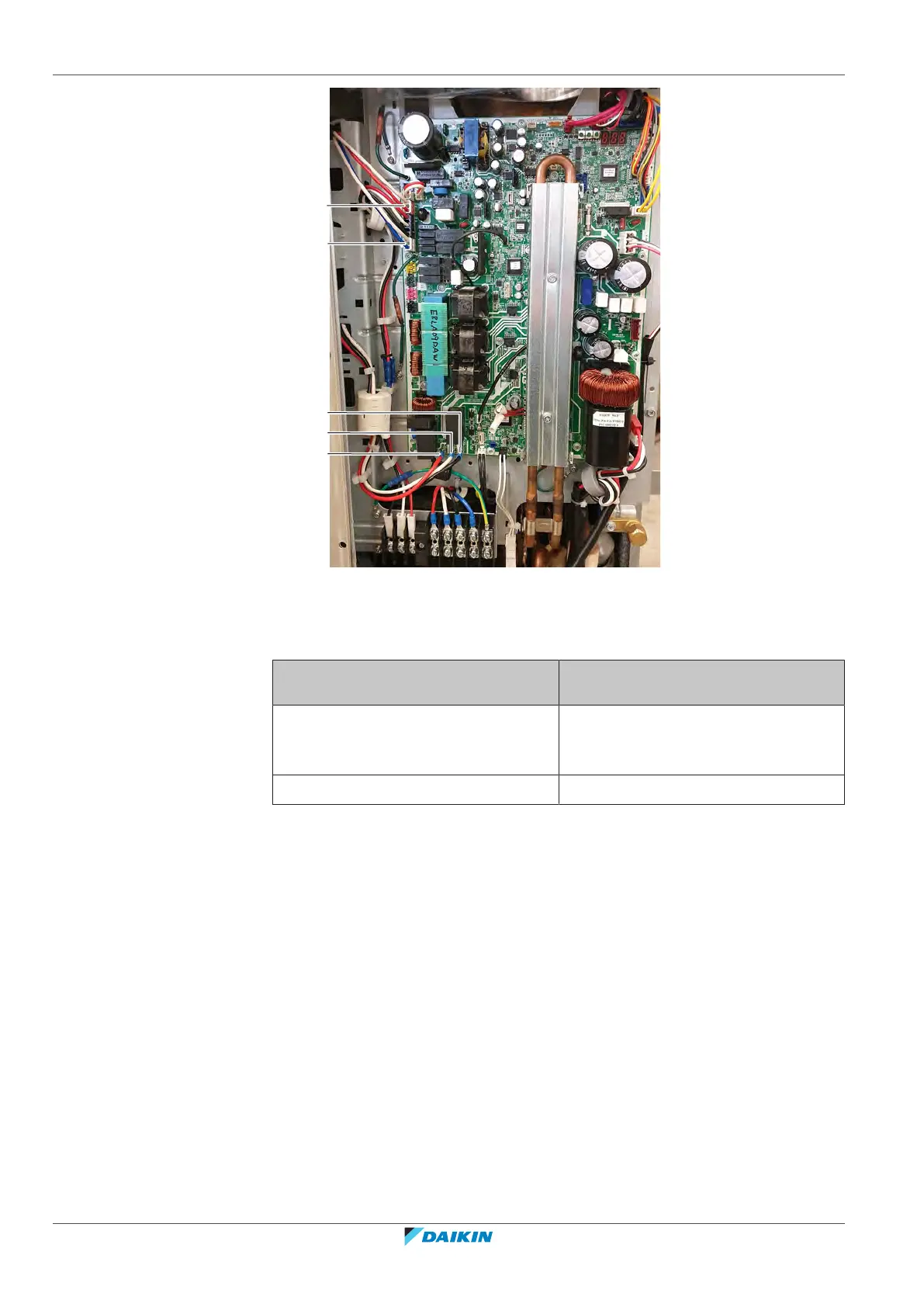
a L1C
b L2C
c L3C
d Connector X801A
e Connector X802A
Is the measured voltage on the PCB
correct?
Action
Yes Return to "Checking
procedures"[4181] of the PCB and
continue with the next procedure.
No Continue with the next step.
5 Measure the output voltage between the phases L1B‑L2B‑L3B on the noise
filter PCB.
Result: All measurements MUST be 400VAC ± 10%.
6 Measure the output voltage on connectors X601 and X602 on the noise filter
PCB.
Result: The measured voltages MUST be 230VAC ± 10%.