Do you have a question about the Daikin ECORICH R 40 Series and is the answer not in the manual?
Classifies safety instructions into DANGER, WARNING, CAUTION, NOTICE.
Highlights dangers and precautions for safe operation and handling.
Outlines DAIKIN's responsibilities and limitations regarding product use and damage.
Specifies qualifications and training required for personnel operating/maintaining the unit.
Details applications where the product should not be used due to safety risks.
Provides general precautions for installation and operation.
Details safety precautions and requirements for electrical installation and wiring.
Safety warnings and precautions related to operating the hydraulic unit.
Safety precautions for performing maintenance inspections.
Guidance on proper disposal of the product as industrial waste.
Explains the importance and location of warning plates on the unit.
Lists technical specifications for different EHU models including capacity, pressure, and flow rate.
Details requirements for usable hydraulic oil, input power, and operating environment.
Illustrates flow rate vs. pressure characteristics for various EHU models.
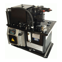
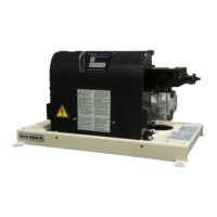
Provides dimensional drawings for the motor pump type unit.
Shows hydraulic circuit diagrams for motor pump and 20L tank unit types.
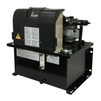
Identifies components of the motor pump type unit from the front view.
Identifies components of the 20L tank unit type from the front view.
Identifies components of the 30L tank unit type from front and top views.
Refers to the chapter on checks upon receiving the product.
Refers to the chapter on transportation and installation procedures.
Refers to the chapter on hydraulic piping.
Refers to the chapter on electric wiring.
Refers to the chapter on trial running.
Refers to the section on setting mode operations.
Details how to check the packaging contents upon receiving the product.
Guides on verifying the product model against the nameplate.
Provides instructions for transporting the product in packaged and unpacked states.
Instructions for moving the product in its original packaging.
Guidelines for safely lifting and moving the hydraulic unit.
General installation guidelines.
Details requirements for adequate ventilation space around the unit.
Instructions for securely mounting the hydraulic unit on a platform.
Explains piping connections and specifications for different unit types.
Step-by-step guide for filling the hydraulic unit with oil.
Details the steps for mounting the exterior covers after wiring.
Presents a schematic of the unit's electrical wiring connections.
Specifies the type and capacity of breakers required for power supply.
Guides on preparing and connecting the main power supply cables.
Instructions for connecting input/output signal cables to the controller.
Explains how to connect digital input signals for unit control.
Details digital output signals for status indication.
Explains how to connect contact output signals for alarm statuses.
Details the powering on procedure and initial checks.
Describes the hydraulic circuit flushing process.
Outlines the procedure for changing the hydraulic oil.
Explains how to bleed air from the hydraulic circuit.
Identifies parts of the operation panel and their functions.
Lists the available modes and how to switch between them.
Lists the available modes (Regular, Monitor, Setting, Alarm).
Illustrates how to switch between different operation panel modes.
Describes the display indications in the regular operation mode.
Overview of the monitor mode functionality.
Lists all available items that can be monitored on the panel.
Step-by-step guide for using the monitor mode on the operation panel.
Overview of the setting mode functionality.
Details how to navigate and change parameters in the setting mode.
Explains how to set pressure and flow rate parameters for PQ selection.
Overview of the alarm mode functionality.
Illustrates how to check alarm history and related data.
A comprehensive list of adjustable parameters with their codes, ranges, and details.
How to set pressure and flow rate parameters for PQ selection.
Explains parameters for setting pressure/flow rate at PQ number switching.
Describes how to select PQ numbers using digital input signals.
Details the parameter for adjusting solenoid valve response delay.
Explains how to control the motor pump using digital input signals.
How the unit outputs alarms and warnings via digital/contact outputs.
Describes contact output signals for alarm and warning statuses.
Details digital output signals for status indication.
Explains how to select alarm/warning outputs via parameter settings.
Describes how the pressure switch function operates and its parameters.
How to adjust pressure retention and responsiveness.
Steps for preparing the unit for pressure response adjustment.
Provides guidelines for setting the P58 parameter based on discharge port length.
Explains how to suppress pressure surge by adjusting start-up time.
Details the function and parameters for detecting dry operation.
Explains output signals from protection functions based on parameter settings.
Guides on how alarms are displayed on the operation panel.
Lists alarm codes, their causes, and recommended corrective actions.
Lists warning codes, their causes, and recommended corrective actions.
Provides a schedule and instructions for periodic maintenance tasks.
Outlines periodic cleaning and replacement tasks for various components.
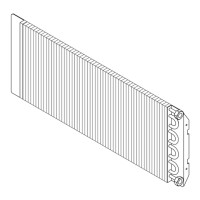
Specific maintenance procedures for the oil cooler.
Step-by-step instructions for removing the oil cooler.
Details how to disassemble the oil cooler.
Instructions for cleaning the oil cooler core.
Instructions for cleaning the DC fan.
Steps for reassembling the oil cooler after cleaning.
Maintenance procedures for the oil cooler filter.
Instructions for removing the oil cooler filter.
Instructions for cleaning the oil cooler filter.
Instructions for attaching the oil cooler filter after cleaning.
Maintenance procedures for the oil filler port cum air breather.
Instructions for removing and fitting the oil filler port cap.
Instructions for cleaning the oil filler port strainer.
Maintenance procedures for the suction strainer.
Details how to remove the suction strainer for cleaning.
Instructions for cleaning the suction strainer.
Steps for reassembling the suction strainer.
Guides on how to adjust the safety valve's pressure setting.
Instructions for mounting a fixed throttle accessory.
Illustrates timing charts for unit startup with different alarm output settings.
Shows timing charts for PQ selection switching based on digital inputs.
Introduces the Hybrid-Win software for system monitoring and control.
| Refrigerant | R-410A |
|---|---|
| Cooling Capacity Range | 40 - 130 kW |
| Compressor Type | Scroll |
| Sound Pressure Level | 65-75 dB(A) at 1m distance |
| Applications | Industrial process cooling |
| Series | ECORICH R 40 Series |
| Type | Air Cooled Chiller |