7 Installation
Installer reference guide
41
ERGA04~08DAV3(A) + EHVH/X04+08S18+23DA
Daikin Altherma – Low temperature split
4P495248-1 – 2017.12
Typical workflow
Connecting the electrical wiring typically consists of the following
stages:
1 Making sure the power supply system complies with the
electrical specifications of the heat pump.
2 Connecting the electrical wiring to the outdoor unit.
3 Connecting the electrical wiring to the indoor unit.
4 Connecting the main power supply.
5 Connecting the backup heater power supply.
6 Connecting the shut–off valves.
7 Connecting the electrical meters.
8 Connecting the domestic hot water pump.
9 Connecting the alarm output.
10 Connecting the space cooling/heating ON/OFF output.
11 Connecting the changeover to an external heat source.
12 Connecting the power consumption digital inputs.
13 Connecting the safety thermostat.
7.9.2 About electrical compliance
Only for ERGA04~08DAV3 (not for ERGA04~08DAV3A)
Equipment complying with EN/IEC 61000‑3‑12 (European/
International Technical Standard setting the limits for harmonic
currents produced by equipment connected to public low-voltage
systems with input current >16A and ≤75A per phase.).
Only for the backup heater of the indoor unit
See "7.9.9 To connect the backup heater power supply" on
page44.
7.9.3 Precautions when connecting the
electrical wiring
INFORMATION
Also read the precautions and requirements in the
following chapters:
▪ General safety precautions
▪ Preparation
DANGER: RISK OF ELECTROCUTION
WARNING
ALWAYS use multicore cable for power supply cables.
7.9.4 Guidelines when connecting the electrical
wiring
Keep the following in mind:
▪ If stranded conductor wires are used, install a round crimp-style
terminal on the end of the wire. Place the round crimp-style
terminal on the wire up to the covered part and fasten the terminal
with the appropriate tool.
a Stranded conductor wire
b Round crimp-style terminal
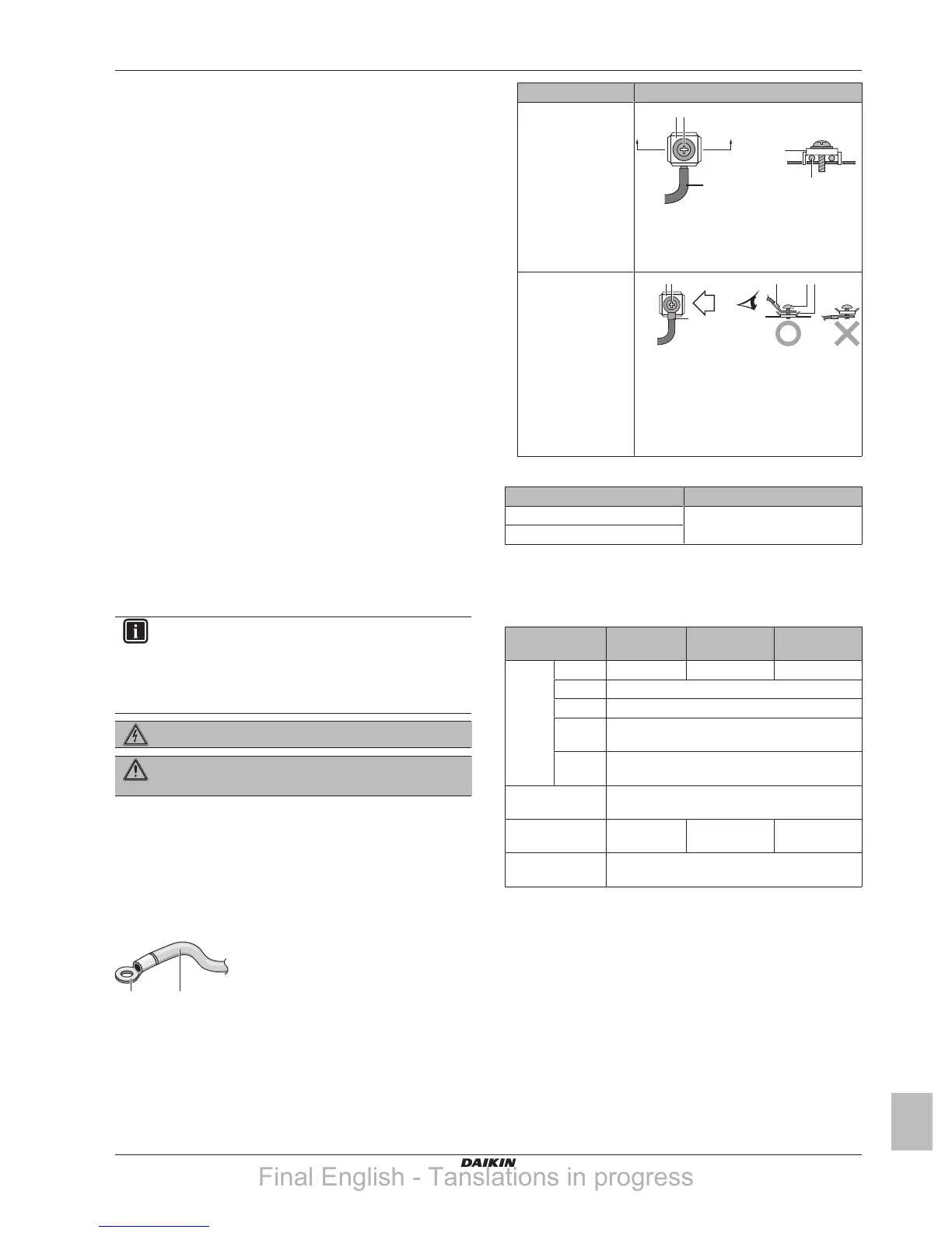
▪ Use the following methods for installing wires:
Wire type Installation method
Single-core wire
a Curled single-core wire
b Screw
c Flat washer
Stranded conductor
wire with round
crimp-style terminal
a Terminal
b Screw
c Flat washer
O Allowed
X NOT allowed
Tightening torques
Item Tightening torque (N•m)
M4 (X1M) 1.2~1.5
M4 (earth)
7.9.5 Specifications of standard wiring
components
Component ERGA04 +
06DAV3
ERGA08DAV3 ERGA04~08D
AV3A
Power
supply
cable
MCA
(a)
19.9A 24.0A 15.9A
Voltage 230V
Phase 1~
Frequen
cy
50Hz
Wire
sizes
Must comply with applicable legislation
Interconnection
cable
Minimum cable section of 1.5mm² and
applicable for 230V
Recommended
field fuse
20A 25A 16A
Earth leakage
circuit breaker
Must comply with applicable legislation
(a) MCA=Minimum circuit ampacity. Stated values are
maximum values (see electrical data of combination with
indoor units for exact values).
7.9.6 To connect the electrical wiring on the
outdoor unit
1 Remove the switch box cover.
Final English - Tanslations in progress
 Loading...