7 Installation
Installer reference guide
45
ERGA04~08DAV3(A) + EHVH/X04+08S18+23DA
Daikin Altherma – Low temperature split
4P495248-1 – 2017.12
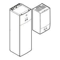
Model (power
supply)
Connections to backup heater power
supply
*9W (3N~400V)
3N~, 50 Hz
400 V AC
SWB
Q1DI
L1 L2 L3 N
1
2
3
4
5
6
7
8
F1B
II I I
X6M
2
1
K5M
4
3
6
5
14
13
F1B Overcurrent fuse (field supply). Recommended fuse for *3V
models: 2‑pole; 20A; curve 400V; tripping class C.
Recommended fuse for *6V and *9W models: 4‑pole; 20A;
curve 400V; tripping class C.
K1M Contactor (in the lower switch box)
K5M Safety contactor (in the lower switch box)
Q1DI Earth leakage circuit breaker (field supply)
SWB Switch box
X6M Terminal (field supply)
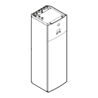
7.9.10 To connect the shut-off valve
1 Connect the valve control cable to the appropriate terminals as
shown in the illustration below.
NOTICE
Wiring is different for a NC (normal closed) valve and a NO
(normal open) valve.
2 Fix the cable with cable ties to the cable tie mountings.
7.9.11 To connect the electrical meters
INFORMATION
In case of an electrical meter with transistor output, check
the polarity. The positive polarity MUST be connected to
X5M/6 and X5M/4; the negative polarity to X5M/5 and
X5M/3.
1 Connect the electrical meters cable to the appropriate terminals
as shown in the illustration below.
2 Fix the cable with cable ties to the cable tie mountings.
7.9.12 To connect the domestic hot water pump
1 Connect the domestic hot water pump cable to the appropriate
terminals as shown in the illustration below.
2 Fix the cable with cable ties to the cable tie mountings.
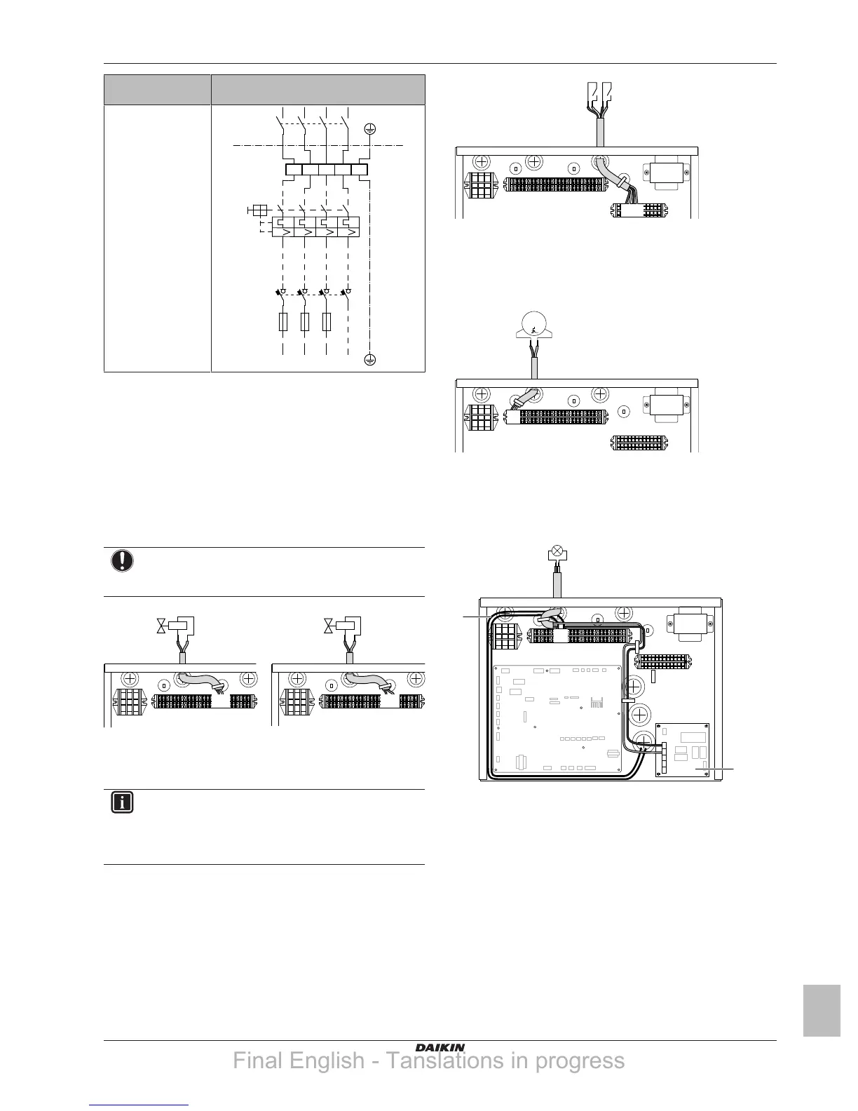
7.9.13 To connect the alarm output
1 Connect the alarm output cable to the appropriate terminals as
shown in the illustration below.
X1M
X2M
A4P
X5M
X1M
YC Y1 Y2 Y3 Y4
Y1
YC
a
7 9
b
a Installation of EKRP1HB is required.
b Prewiring between X2M/7+9 and Q1L (=thermal protector
backup heater). Do NOT change.
2 Fix the cable with cable ties to the cable tie mountings.
7.9.14 To connect the space cooling/heating ON/
OFF output
1 Connect the space cooling/heating ON/OFF output cable to the
appropriate terminals as shown in the illustration below.
Final English - Tanslations in progress
 Loading...