11 | Technical data
Installer and user reference guide
53
FCAG35~140BVEB
Split system air conditioners
4P561448-1B – 2021.07
11 Technical data
▪ A subset of the latest technical data is available on the regional Daikin website
(publicly accessible).
▪ The full set of latest technical data is available on the Daikin Business Portal
(authentication required).
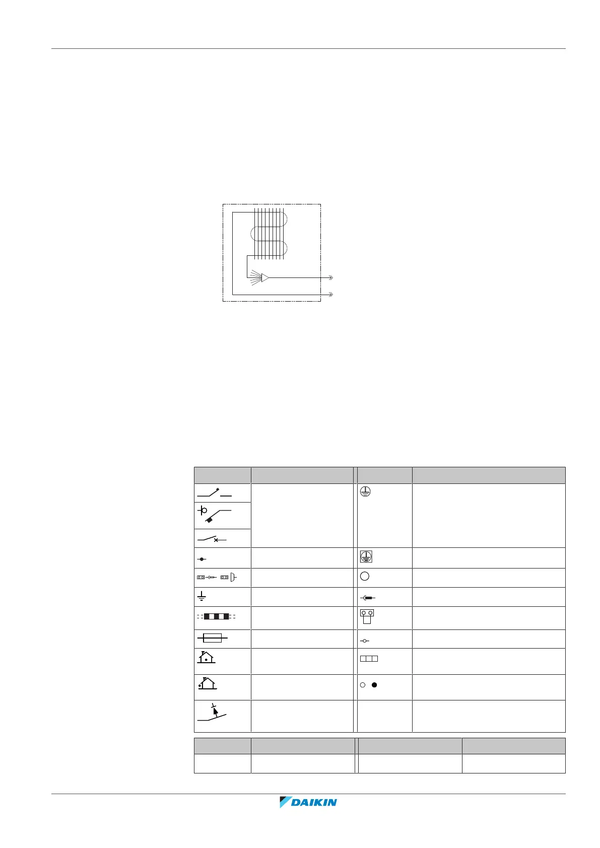
11.1 Piping diagram: Indoor unit
a Liquid pipe connection
b Gas pipe connection
c Heat exchanger
11.2 Wiring diagram
11.2.1 Unified wiring diagram legend
For applied parts and numbering, refer to the wiring diagram on the unit. Part
numbering is by Arabic numbers in ascending order for each part and is
represented in the overview below by "*" in the part code.
Symbol Meaning Symbol Meaning
Circuit breaker Protective earth
Connection Protective earth (screw)
Connector
Rectifier
Earth Relay connector
Field wiring Short-circuit connector
Fuse Terminal
Indoor unit Terminal strip
Outdoor unit Wire clamp
Residual current
device
Symbol Colour Symbol Colour
BLK Black ORG Orange