15 Commissioning
Installation and operation manual
18
FDA200+250AXVEB
Split system air conditioners
3P580564-1E – 2022.11
b
c
P
1
P
2
d
P
1
P
2
P
1
P
2
P
1
P
2
a
1 2 3 L N
1 2 3
1 2 3 L N
1 2 3
1 2 3 L N
1 2 3
b
b
c
a
b
c
a
b
c
e
L N
b
c
e
L N
b
c
e
L N
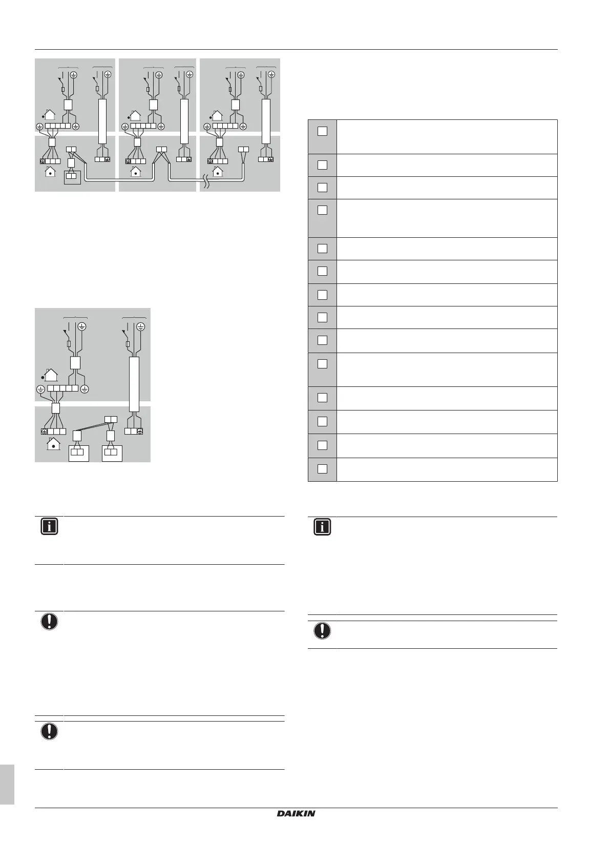
a Power supply
b Main switch
c Residual current device
d User interface
e Separate power supply
▪ All indoor units operate according to the user interface
▪ The thermistor reading of room temperature is effective only for
the indoor unit connected to the user interface.
Control with 2 user interfaces: 2 user interfaces control 1
indoor unit
1 2 3
b
c
1 2 3
P
1
P
2
P
1
P
2
P
1
P
2
d d
a
L N
b
c
e
L N
a Power supply
b Main switch
c Residual current device
d User interface
e Separate power supply
INFORMATION
In case of group control, it is not necessary to assign a
group address to the indoor unit. The group address is
automatically set when the power is turned on.
15 Commissioning
NOTICE
General commissioning checklist. Next to the
commissioning instructions in this chapter, a general
commissioning checklist is also available on the Daikin
Business Portal (authentication required).
The general commissioning checklist is complementary to
the instructions in this chapter and can be used as a
guideline and reporting template during commissioning and
hand-over to the user.
NOTICE
ALWAYS operate the unit with thermistors and/or pressure
sensors/switches. If NOT, burning of the compressor might
be the result.
15.1 Checklist before commissioning
1 After the installation of the unit, check the items listed below.
2 Close the unit.
3 Power up the unit.
You have read the complete installation and operation
instructions described in the installer and user reference
guide.
The indoor unit is properly mounted.
The outdoor unit is properly mounted.
The drain piping is properly installed and insulated, and
drainage flows smoothly. Check for water leaks.
Possible consequence: condensate water might drip.
The ducting is properly installed and insulated.
The refrigerant pipes (gas and liquid) are installed
correctly and thermally insulated.
There are NO refrigerant leaks.
There are NO missing phases or reversed phases.
The system is properly earthed and the earth terminals
are tightened.
The fuses or locally installed protection devices are
installed according to this document, and have NOT been
bypassed.
The power supply voltage matches the voltage on the
identification label of the unit.
There are NO loose connections or damaged electrical
components in the switchbox.
There are NO damaged components or squeezed
pipes on the inside of the indoor and outdoor units.
The stop valves (gas and liquid) on the outdoor unit are
fully open.
15.2 To perform a test run
INFORMATION
▪ Perform the test run according to the instructions in the
connected user interface manual.
▪ The test run is only completed if there is no malfunction
code displayed on the user interface.
▪ See the service manual for the complete list of error
codes and a detailed troubleshooting guideline for each
error.
NOTICE
Do NOT interrupt the test run.
16 Configuration
16.1 Field setting
Make the following field settings so that they correspond with the
actual installation setup and with the needs of the user:
▪ External static pressure setting using:
▪ Airflow automatic adjustment setting
▪ User interface


 To Next Page