6 English
4. PREPARATIONS BEFORE INSTALLATION
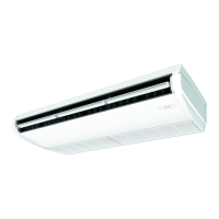
(1) Relation of holes for indoor unit, suspension bolt position, piping and wiring.
(2) Make holes for suspension bolts, refrigerant and drain piping, and wiring.
• Refer to the paper pattern for installation.
• Select the location for each of holes and open the holes in the ceiling.
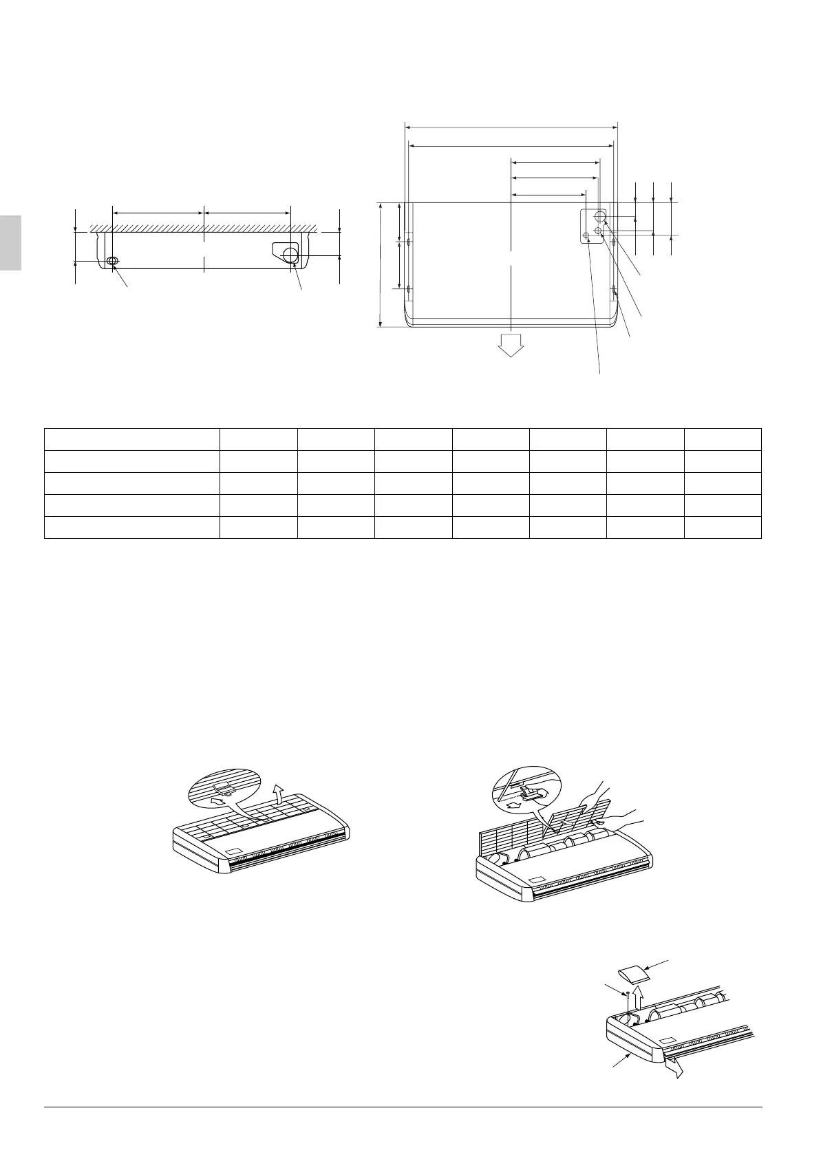
(3) Remove the parts from the indoor unit.
(3-1) Detach the suction grille.
• Slide the locking knobs (×2) on the suction grille inward (direction of arrows) and lift upwards.
(Refer to Fig. 1)
• With the suction grille open, remove the suction grille forward, holding on to the rear tabs on the suction
grille. (Refer to Fig. 2)
(3-2) Remove the dressing boards (left and right).
• After removing the securing screws for the
dressing boards (one each), pull them forward
(in the direction of the arrow) and remove
them. (Refer to Fig. 3)
• Take out the accessories.
Model A B C D E F G
Type 35, 45, 50 960 920 390 375 310 400 375
Type 60, 71 1160 1120 490 475 410 500 475
Type 100 1400 1360 610 595 530 620 595
Type 125 1590 1550 705 690 625 715 690
A
B
85
160
185
210260
680
C
D
E
Top side drain
piping hole
Top gas piping hole
Top liquid piping hole
Suspension
bolt (×4)
Air outlet
False ceiling view
(Length : mm)
160
135
FG
Rear side piping hole
Left side piping hole
Front view
Fig. 1 Fig. 2
Accessories
Dressing board securing
screw (M4)
Dressing board
Fig. 3
01_EN_3PN06588-3E.fm Page 6 Tuesday, June 27, 2006 4:45 PM
 Loading...