Do you have a question about the Daikin FTK09P5VL and is the answer not in the manual?
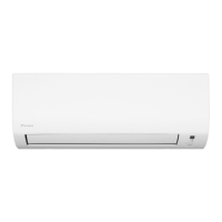
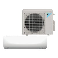
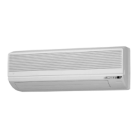
This document is a service manual for Daikin air conditioning indoor units, specifically detailing the removal procedure for various components. The manual covers models with cooling-only and heat pump functions, including FTK09P5VL, FTK12P5VL, FTK18P5VL for cooling, and FTH09P5VL, FTH12P5VL, FTH18P5VL, FTX09N5VL, FTX12N5VL, FTX18N5VL for heat pump models. The units are described as 9000/12000/18000 Btu/h Class indoor units, featuring Inverter technology and designed as Wall Mounted Type.
The manual outlines a step-by-step removal procedure for several key components, emphasizing safety precautions such as waiting 10 minutes after turning off all power supplies before disassembling. This waiting period is crucial to prevent electrical shock or explosion.
The first step involves removing the air filters and the front panel. To remove the air filters, they must be unfixed from two hooks and pulled out. The air filter is designed to be inserted easily by aligning it along the guides, and the "FRONT" mark should face up. For the front panel, two screws need to be removed, and then the panel is unfixed from three hooks at the top. The upper part of the front grille is pulled out, lifted up from the lower part, and then removed. The convex marks on the front panel indicate the position of the hooks. When reassembling, it's important to ensure all three hooks are fastened.
The front grille removal is integrated with the front panel removal, as described above. The process involves removing two screws and then unfastening three hooks at the top. The upper part of the front grille is pulled out, lifted from the lower part, and then removed. The convex marks on the front panel help locate the hooks. For reassembly, ensure all three hooks are securely fastened.
Removing the horizontal blade requires releasing the center shaft by bending the horizontal blade slightly. Then, the left and right shafts are released. The installation procedure for the horizontal blade involves fitting the right shaft first, rotating the horizontal blade so the shaft fits correctly, and then fitting the horizontal blade to the center and left shafts.
The electrical box removal is a multi-step process. First, the service cover is disconnected by removing a screw. Then, the connecting wire and wire fixture are disconnected, followed by the removal of four screws from the terminal board. Next, the electrical box itself is removed by detaching two earth/ground wires from the front slit at the top of the electrical box. When reassembling, it's important to insert the earth/ground wires in the front slit.
Further steps for the electrical box involve pulling out the indoor heat exchanger thermistor, which is secured by a clip. The thermistor harness is then released from the pipes of the heat exchanger ASSY and from the back slit at the top of the electrical box. When reassembling, ensure the thermistor harness is inserted in the back slit and passed below the pipes of the heat exchanger ASSY. Finally, four hooks are unfastened to remove the electrical box cover. When reassembling, make sure the four hooks are securely fastened.
The manual also details disconnecting the fan motor connector ([S200]) and swing motor connector ([S6]), and releasing their harnesses from the hooks. The screw of the electrical box is then removed, and the box is slightly lifted upward and removed. When reassembling, ensure the hook is securely fastened and the two hooks of the bottom frame are securely fastened.
This section covers the removal of the control PCB and display PCB, as well as the swing motor. To remove the control PCB, all four terminals are disconnected, and the wires are released from the three hooks. Then, the connector [S26] is removed, and four hooks are unfastened to remove the control PCB. When reassembling, ensure the control PCB fits to the four projections.
For the display PCB ASSY, three hooks are unfixed, and the display PCB ASSY is removed. The harnesses of the display PCB ASSY are then released from the two hooks. To remove the display PCB, it is turned over, and three hooks are unfixed. Finally, the swing motor is removed by unscrewing it.
This is a critical section with several warnings. It emphasizes waiting 10 minutes after turning off all power supplies before disassembling. It also warns that in pump-down work, the refrigerant pipe must be disconnected with the compressor operating and the stop valve open. If refrigerant leaks, repair the spot of leaking, then collect all refrigerant from the unit. When removing or reinstalling the indoor heat exchanger, wear gloves and wrap the indoor heat exchanger with cloths to prevent injury.
The procedure involves disconnecting the refrigerant piping and removing two screws. The drain hose is pulled out and disconnected, and the open ends of the drain hose are wrapped with plastic sheets to prevent water dripping. The flare nut for gas piping and liquid piping are disconnected, and the open ends of both pipes and the unit are protected from moisture intrusion. When reassembling, place a plastic sheet around the drain hose to prevent wetting the floor with remaining drain. The indoor unit should be held up with a piece of wood, and the drain hose can be disconnected from the back of the unit. The removal work should be carried out with two wrenches.
Further steps include detaching the indoor unit from the installation plate. To remove the indoor heat exchanger, two hooks and the piping fixture on the back of the indoor unit are unfixed. The auxiliary piping is slightly pulled out. Two screws on the left side are removed, and the hook on the rear side is unfixed. Finally, the hook on the right side is unfixed, and the indoor heat exchanger is lifted up. When reassembling, make sure the hook is fastened.
To remove the fan rotor and fan motor, first, the screw of the right side plate is removed. Then, the hook is unfixed, and the right side plate is removed. The fan rotor and fan motor are then removed. The fan motor has three projections on the right side, and the fan rotor has a rotating shaft on the left side.
Next, the fan motor stator ASSY is pulled out and removed. Two hooks are unfixed, and the fan motor stator ASSY is disassembled. This involves separating the fan motor cover (body), bearing rubber cushion, fan motor stator, and fan motor cover (cap).
This section details the removal of the fan guards and vertical blade ASSYs. To remove the fan guards, two hooks at the bottom and two hooks at the top are unfixed, and the fan guard is removed. When reassembling, fit the fan guard to the two projections at the top and fasten the two hooks at the bottom. The fan guards are not marked for difference between right and left.
To remove the vertical blade ASSYs, the upper two hooks are unfixed. Each vertical blade ASSY has five fins, and it is impossible to replace only one fin. The vertical blade ASSY is not marked for difference between right and left. Then, three hooks at the shaft mounting part are unfixed by pressing them with a flat screwdriver. Finally, the vertical blade ASSY is removed, followed by the other vertical blade ASSY in the same way.
The document includes a revision history, indicating that the first edition (SI041417E) was released in 01/2015. A revised version (SI041417EA) was released in 12/2016, which included model additions: FTK09/12/18P5VL, FTH09/12/18P5VL.
The manual also includes important cautions regarding product corrosion. Air conditioners should not be installed in areas where corrosive gases, such as acid gas or alkaline gas, are produced. If the outdoor unit is to be installed near the sea, direct exposure to the sea breeze should be avoided. If installation near the sea is unavoidable, contact your local distributor.
Daikin products are manufactured for export to numerous countries worldwide. Prior to purchase, customers should confirm with their local authorized importer, distributor, and/or retailer whether the product conforms to applicable standards and is suitable for use in the region where it will be used. The document states that it does not purport to exclude, restrict, or modify any applicable legal legislation.
Users are advised to ask a qualified installer or contractor to install the product and not to try to install it themselves. Improper installation can result in water or refrigerant leakage, electrical shock, fire, or explosion. Only genuine Daikin parts and accessories, or those approved by Daikin, should be used. Unauthorized parts and accessories, or improper installation of parts and accessories, can result in water or refrigerant leakage, electrical shock, fire, or explosion.
Finally, users are reminded to read the user's manual carefully before using the product, as it provides important safety instructions and warnings. For any inquiries, users should contact their local importer, distributor, and/or retailer.
| Brand | Daikin |
|---|---|
| Model | FTK09P5VL |
| Category | Air Conditioner |
| Language | English |