J
Joseph SmithAug 13, 2025
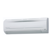
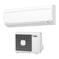
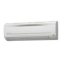
Why is my Daikin FTKS20CVMB Air Conditioner outdoor unit leaking water?
- CcainjacobAug 13, 2025
In HEAT mode, the frost on the outdoor unit melts into water or steam during defrost operation. In COOL or DRY mode, moisture in the air condenses into water on the cool surface of the outdoor unit piping and drips.