Do you have a question about the Daikin FTKS50D2V1W and is the answer not in the manual?
Lists and describes various system malfunctions and their detection.
Lists common problems and their corresponding solutions.
Explains methods for checking unit functions and diagnosing issues.
Details the first method for service checks using remote control codes.
Details the second method for service checks using sound diagnosis.
Lists error codes displayed on the remote control and their meanings.
Provides a comprehensive list of error codes and their fault descriptions.
Offers detailed troubleshooting steps for various symptoms.
Troubleshooting specific to indoor unit issues.
Troubleshooting specific to outdoor unit issues.
Addresses issues related to the indoor unit's printed circuit board.
Troubleshoots freeze-up or high pressure control issues.
Addresses problems related to the fan motor.
Troubleshoots issues with indoor unit thermistors.
Troubleshoots communication errors between indoor and outdoor units.
Troubleshoots freeze-up protection control issues.
Addresses issues related to the outdoor unit's printed circuit board.
Troubleshoots compressor overload issues.
Addresses issues related to compressor lock.
Troubleshoots issues with the DC fan lock.
Addresses issues related to input over current detection.
Troubleshoots issues related to discharge pipe temperature control.
Addresses high pressure control issues during cooling.
Troubleshoots abnormalities in the compressor sensor system.
Addresses issues related to the position sensor.
Troubleshoots issues with CT or related components.
Addresses issues with outdoor unit thermistors.
Troubleshoots issues related to electrical box temperature rise.
Addresses issues related to radiation fin temperature rise.
Troubleshoots issues related to output over current detection.
Addresses issues related to insufficient gas.
Troubleshoots low or over-voltage detection issues.
Addresses signal transmission errors on the outdoor unit PCB.
| Cooling Capacity | 5.0 kW |
|---|---|
| Heating Capacity | 5.6 kW |
| Power Supply | 220-240 V, 50 Hz |
| Refrigerant | R32 |
| Outdoor Unit Noise Level | 48 dB(A) |
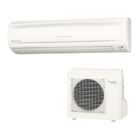
| Type | Split |
| Outdoor Unit Dimensions (WxHxD) | 285 mm |