
A
Adam MilesAug 2, 2025
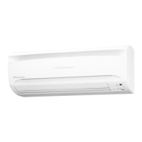
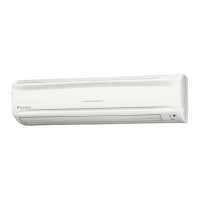
Why is my Daikin FTKS50BVMA Air Conditioner outdoor unit leaking water?
- JJason GreenAug 2, 2025
In HEAT mode, frost on the outdoor unit melts into water or steam when the Daikin air conditioner is in defrost operation. In COOL or DRY mode, moisture in the air condenses into water on the cool surface of outdoor unit piping and drips.